 FREE 1 to 3-Day Delivery on Orders $119+ Details
Best Sellers


How to Install a 3D Carbon Boy Racer Body Kit on Your 2005-2009 Mustang GT
Installation
| QTY | PART # | DESCRIPTION |
|---|---|---|
| 1 | 690001 | FRONT BUMPER REPLACEMENT |
| 1 | 691002 | SIDE SKIRT RIGHT |
| 1 | 691003 | SIDE SKIRT LEFT |
| 1 | 691004 | DOOR CAP RIGHT |
| 1 | 691005 | DOOR CAP LEFT |
| 1 | 691006 | RIGHT FRONT FLARE |
| 1 | 691007 | LEFT FRONT FLARE |
| 1 | 691008 | RIGHT REAR FLARE |
| 1 | 691009 | LEFT REAR FLARE |
| 1 | 691010 | REAR BUMPER REPLACEMENT |
CAUTION!!!! IF A HEATED SPRAY BOOTH IS USED FOR BAKING THE PRIMER OR PAINT, DO NOT BAKE OR CURE GREATER THAN 120 F DEGREES FARENHEIT. THE PARTS CAN BE DISTORTED AND PERMANENTLY DAMAGED.
PREPPING THE KIT PRIOR TO PAINT
The first step is to inspect the parts to make sure you have the correct parts. Refer to the part numbers on the back of the parts to confirm the Year – Make – Model. Parts that are prepped and painted cannot be returned or exchanged.
Using lacquer thinner and a clean cloth – clean the tape flange surface on the back of each part where the double sided tape will be applied. Using 1” masking tape, apply the tape 1/8” below the top edge of the part. This will protect the tape flange from getting contaminated during the prepping and painting process. Refer to Prepping and Painting Instructions for “Step by Step” procedures
FRONT BUMPER REPLACEMENT
HARDWARE SUPPLIED
- (4) SELF TAPPING #8 X ¾” SCREWS
- (1) ALUMINUM MESH GRILL (Requires Painting)
- (9) ½” X #8 – SCREWS
- (9) ¾” X 5/16” FLAT WASHERS
- (4) ¼ 20 X ½” SCREWS
- (4) NUTS
STEP 1) Open the hood and remove the trim panel over the radiator by using a clip puller - remove the (6) plastic push clips. Remove the (2) 10mm screws that secure the top of the front bumper. Remove the (3) Phillips head screws in each wheel well that secure the bumper to the inner fender panel. On GT Models locate and remove the (4) 5.5mm screws under the front of the bumper that secure the bumper to the wind deflector panel. Locate and remove the 10mm bolts that secure the bumper to the bottom of the fender on each side.
STEP 2) Carefully pull the bumper down and slide the bumper forward enough to access the wiring connectors on the side marker lights. Disconnect the plug from the side marker lights. On GT models disconnect the wiring harness on the driving lights. Now remove the bumper completely from the car. Remove the front marker lights and the front grille from the bumper.
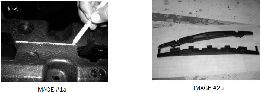
STEP 3) Remove the black bumper impact absorber from the bumper. Using a grease pencil, draw a line along the top edge of the impact absorber (See Image #1a). Using a band saw cut off the bottom of the absorber and discard (See Image # 2a) for where to cut. Reinstall the absorber back onto the reinforcement.
STEP 4) Take the supplied aluminum mesh grille and using a red scotch brite, scuff the surface of the grille and using an adhesion promoter, spray the grille. After applying the adhesion promoter, we recommend that you use Trim Black to spray the grille black.
STEP 5) Lay the new 3d bumper replacement upside down. Place the supplied aluminum mesh grille inside the bumper. Check fit the grille in the opening. Using a screw gun with a Phillips head tip and the (9) 1/2” screws and washers provided, secure the aluminum grille to the front bumper. (See Images #3a-4a).
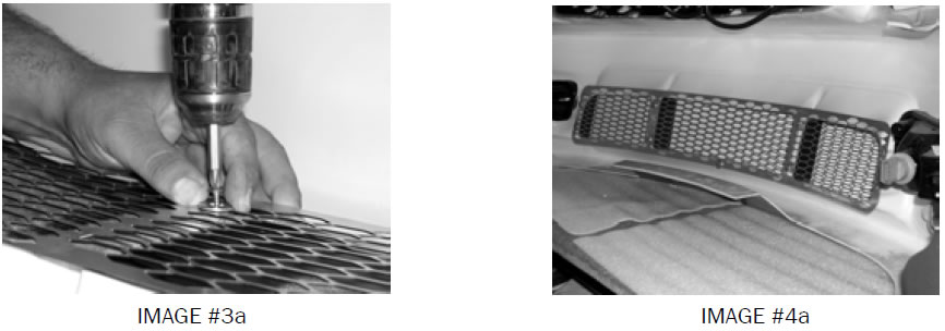
STEP 6) Install the original marker lights on the brackets that have been pre-applied to the bumper. Secure the lights with the supplied (4) 1/4 20 x3/4” screws and nuts to the two holes on the brackets. (See Image #5a & #6a) Place the original factory grille into the opening on the bumper. Press the grille through the holes on the 3d Bumper to make sure that the grille is secure on the new 3dCarbon bumper. On GT Models reconnect the Fog - Driving lights.
STEP 7) Place the bumper on the vehicle. Do not secure the bumper in the wheel wells yet. Final installation of the bumper will occur after installation of the fender flares is complete. It may be necessary to file the holes to ensure good fit of the front bumper against the fender flare
REAR BUMPER REPLACEMENT
HARDWARE SUPPLIED
- (2) 6mm x 30mm HEX DRIVE SCREWS
- (22) ¾” FLAT WASHERS
- (4) #8 X ¾” SELF DRILLING SCREWS
- (2) ALUMINUM SUPPORT BRACKETS
- (2) 3/16” ALUMINUM RIVETS
- (2) RIVET BACKING WASHERS
- (2) ¼” X 20 X 1 – ¼” HEX HEAD BOLTS
- (4) #8 X ¾” SELF TAPPING SCREWS
- (6) PUSH-NUT BOLT RETAINERS
- (2) ¼” x ¾” FLAT WASHERS
STEP 1) Open the trunk and locate the black plastic trim panel that goes around the rear latch. Remove the (6) plastic clips that secure the trim panel. Locate and remove the (4) 11mm nut’s that secure the rear bumper. Locate the wiring harness plug inside the trunk on the right side, disconnect the plug from the connector. Push the plug and grommet through the hole.
STEP 2) Locate and remove the two Phillips head screws in each wheel well that secure the bumper to the body using a 90 degree angle screw gun-Phillips screwdriver tip. Locate and remove the three black plastic clips on the underside of the bumper that secure the three straps to the body. The bumper is now ready to pull off the car.
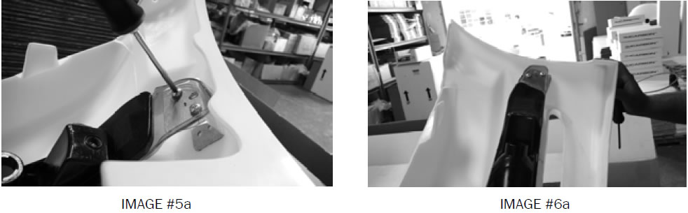
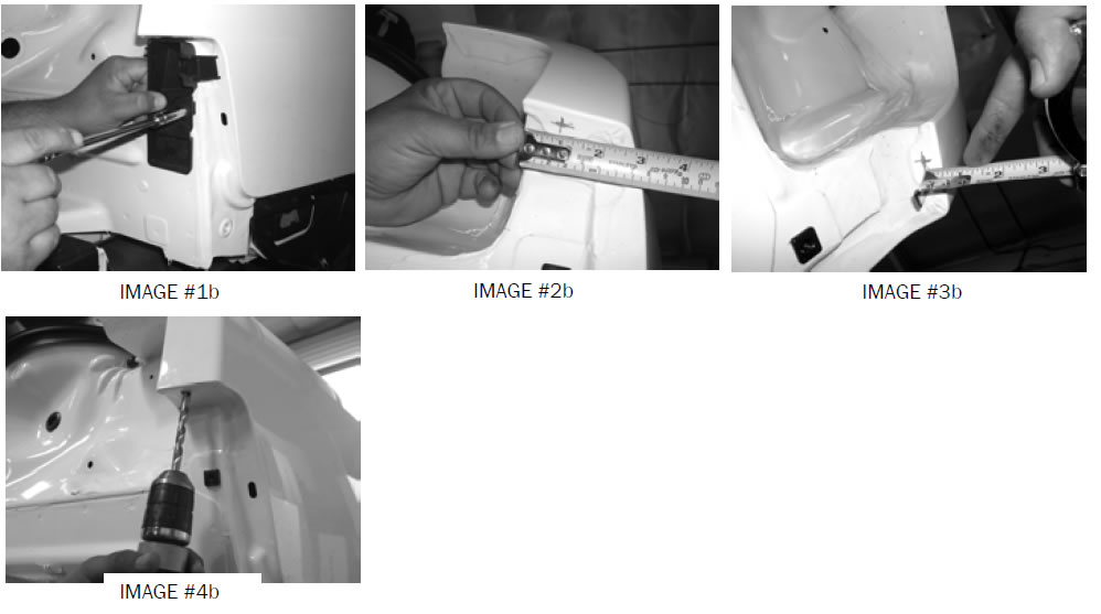
Step 3) Locate the rear black bracket that secures the bumper onto the car and remove. (See Image #1b) Using a tape measure, measure ½” in from the outer edge of the quarter panel. Make a mark with a grease pencil. Measure 1” out from the inner edge of the quarter panel and make a mark. Make sure that you draw lines long enough to ensure that the two marks intersect. (See Image #2b & 3b). Using a 3/8” drill bit, drill where the two lines intersect. (See Image #4b)
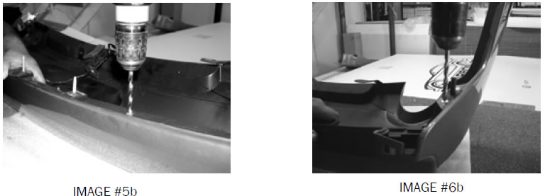
STEP 3) Using a 3/8” drill bit, drill out the (8) aluminum rivets that secure the reinforcement strip on the inside of the rear bumper (See image #5b & 6b ) Drill the tops of the rivets off only, do not drill through the rivets completely. Carefully remove the plastic bracket with the wiring harness.
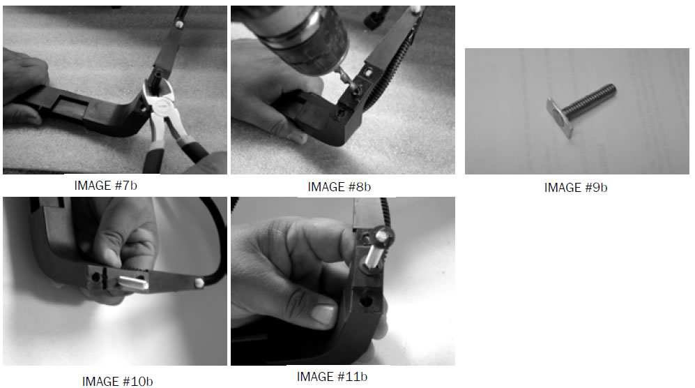
Step 4) Locate and remove the locator pins on the black plastic bracket. (See Image #7b) Using the ¼” drill bit, drill out where the locator pin was located. (See Image #8b) Using the ¼” x 20 x1 ¼ ” stud insert, insert the bolt through the hole previously drilled. (See Image #9b & 10b) Secure by using the pushnut bolt retainer. (See Image #11b).
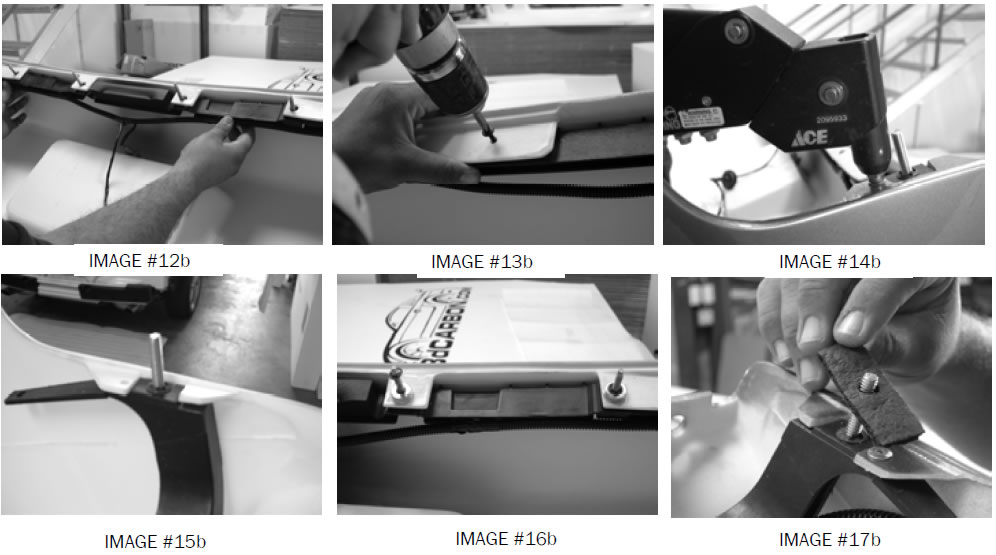
STEP 5) Place the plastic bracket with the wiring harness inside the 3d rear bumper. Reinstall the factory side marker lights into the rear bumper that were previously removed in Step 3. (See Image #12b). Line up the threaded studs on the plastic bracket through the pre drilled holes in the rear bumper. Secure the plastic strip to the inside of the bumper with the (4) #8 x ¾” self tapping screws (See Image #13b).
Align the hole on the end of the bracket with the bottom hole on the bumper tab. Even though the plastic bracket was secured to the original bumper with two rivets, we recommend using only one rivet each side in the bottom pre drilled hole to attach the plastic bracket to the 3d Bumper
The bottom hole was pre drilled by 3dCarbon with a fixture to insure a proper fit. Using a Rivet gun, secure the plastic bracket to the 3d Bumper with (1) 3/16” Rivet on each side with a rivet washer on the back side (See Image #14b & #15b).
Locate the four factory studs that secure the rear bumper to the car and place (4) ¾” flat washers on each of the two center studs. Secure the washers onto the studs using the push nut bolt retainers. (See Image #16b).
Locate the two outer studs and place (3) ¾” washers on each of the studs. Secure the washers using the push nut bolt retainers. Locate and remove the spongy gasket and reinstall it on the new 3dCarbon rear bumper. (See Image #17b)
STEP 7) Place the license plate light into the original location. Using a 1/8” drill bit, drill the two holes that secure the light to the bumper. Secure the light to the bumper with 2 #8x ¾” self tapping screws.
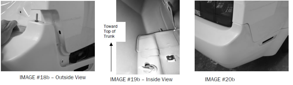
STEP 8) Place the bumper on the car and feed the wires and grommet through the hole. Secure the bumper with the original (4) nuts previously removed from the center of the bumper. Snap the sides of the bumper into the clips on the side of the quarter panel. Secure the rear upper corner of the bumper to the car using the supplied washers and nuts. (See Image #18b & 19c) It may be necessary to file the holes to ensure proper fit of the upper corner of the bumper. Proper installation will appear similar to Image #20b.
STEP 9) To secure the center section of the rear lower to the body remove the two bolts (V8 Models) that secure the exhaust brackets Attach the supplied brackets to the body with the original bolt. Note: On V6 Models -single exhaust, there is not a bolt on the driver side, secure the bracket with a self tapping # 8 x 3/4 self drilling screw. Attach the bottom of the rear bumper to the bracket with a #8 x 3/4” screw on each side.
SIDE SKIRTS
HARDWARE SUPPLIED
- (14) #8 x ¾” SELF DRILLING SCREWS
- (4) 3M 6396 ADHESION PROMOTER
- 3M DOUBLE FACE TAPE
APPLYING THE 3M TAPE TO THE SIDE SKIRTS
After the kit has been prepped and painted, the double face tape should be applied to the parts. The tape is not pre-installed on parts prior to shipping because the tape can be contaminated during the sanding/ priming and painting process.
The first step is to clean the tape flange on the back of the parts where the tape will be applied. Make sure the complete tape flange is clean and free of all primer and paint. Using lacquer thinner on a clean rag, thoroughly clean the tape flanges on all parts of the kit.
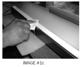
Using the adhesion promoter bottle with felt tip supplied, apply it to the tape flanges – be careful not press too hard causing too much to be applied. The adhesion promoter will leave a thin clear polymer primer film that will increase the bonding strength of the double face tape.(See Image #1c).
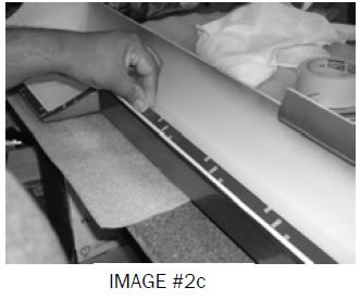
The tape should be applied 1/8” down from the top edge of the part so that it cannot be seen after the kit is installed. The tape should be applied to the flange of each part. Press the tape firmly to the surface to insure good adhesion of the double faced tape. (See Image #2c).
NOTE: For a real clean installation, paint one side of the double face tape roll the color of the paint on the car so that when it is seen from the edge it does not show the grey color of the tape.
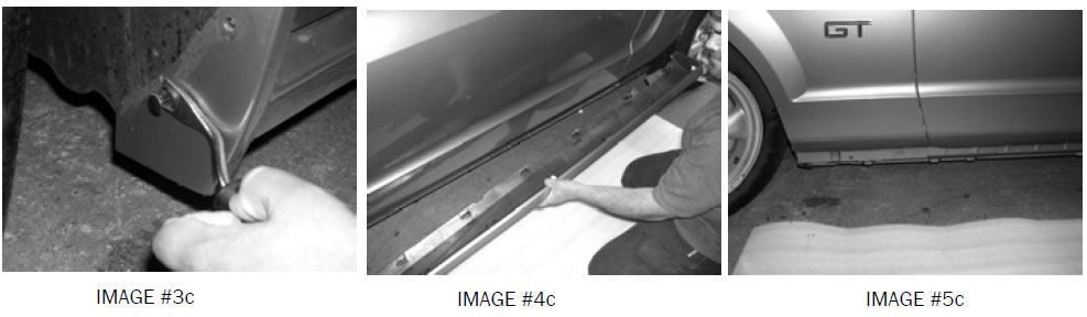
STEP 1) Remove the original factory sides skirts from the car by removing the two clips in the front wheel well then locate and remove the clips from the bottom of the car. Now pull the side skirt away from the car. This will leave some of the clips on the car. Remove these after the side skirt is off the car. (See Images #3c - #5c).
STEP 2) Open the door and test fit the side skirts. Make sure the side skirt is fitted tight to the body from front to rear. Using a grease pencil, draw a line along the top edge of the side skirt for reference during final installation.
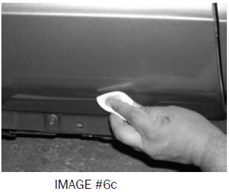
STEP 3) Remove the part from the car and using lacquer thinner on a clean lint-free cloth, wipe the paint surface where the tape will attach. Using the supplied adhesion promoter supplied, apply it to the paint surface where the tape will attach. Peel back tape and install side skirt. Press firmly on car to insure good adhesion of the double-sided tape. (See Images #6c).
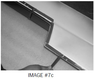
STEP 6) Remove the red plastic backing from the side skirt. Make a small tail on each section of tape. (See Image #7c)
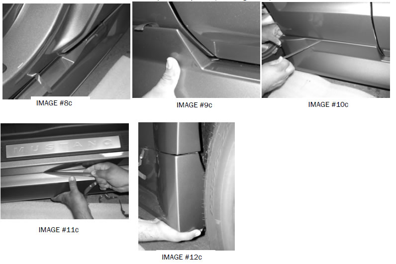
STEP 7) Install the side skirt on the body and align it to the grease pencil lines. Carefully pull the red backing from the tape, and press the side skirt - tape to the paint surface. Align the side skirt by using the door jam as areference, see images #8c – #11c. NOTE: Only pull 6 inches of tape. Final installation will occur after the fender flares have been installed. This will ensure proper positioning of the flares and the side skirts. After the installation of the fender flares, the rest of the tape can be pulled. (See Image #12c)
STEP 8) Secure the side skirt with (2) #8 x ¾” self tapping screws in each wheel well. Locate the urethane flange on the underneath side of the side skirt and secure it to the car by using (3) #8 x ¾” self tapping screws evenly spaced.
STEP 9) Repeat step 1-8 for opposite side.
DOOR CAPS
HARDWARE SUPPLIED
- (4) 3M 6396 ADHESION PROMOTER
- 3M DOUBLE FACE TAPE
APPLYING THE 3M TAPE TO THE DOOR CAPS
After the kit has been prepped and painted, the double face tape should be applied to the parts. The tape is not pre-installed on parts prior to shipping because the tape can be contaminated during the sanding/ priming and painting process.
he first step is to clean the tape flange on the back of the parts where the tape will be applied. Make sure the complete tape flange is clean and free of all primer and paint. Using lacquer thinner on a clean rag, thoroughly clean the tape flanges on all parts of the kit.
Using the adhesion promoter bottle with felt tip supplied, apply it to the tape flanges – be careful not press too hard causing too much to be applied. The adhesion promoter will leave a thin clear polymer primer film that will increase the bonding strength of the double face tape.
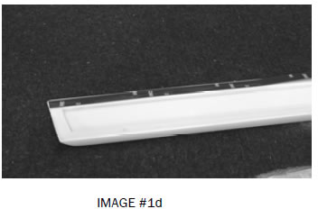
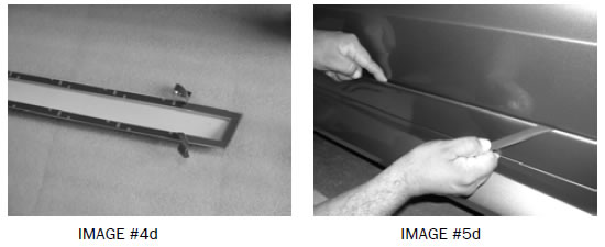
The tape should be applied 1/8” down from the top edge of the part so that it cannot be seen after the kit is installed. The tape should be applied to the flange of each part. Press the tape firmly to the surface to insure good adhesion of the double faced tape. (See Image #1d).
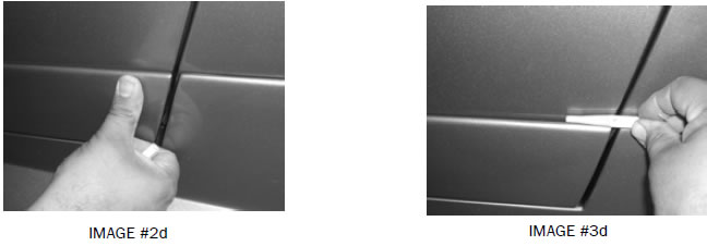
STEP 1) Place the door cap on the body and align it along the bottom of the door. The top edge should be even with the top of the side skirt - front and rear. (See Image # 2d) Once the cap is aligned mark the surface of the paint with a grease pencil then remove the door cap. (See Image #3d)
STEP 2) Using Lacquer thinner on a clean rag quickly wipe the paint on the body where the double face tape will come in contact. Be careful not to remove the grease pencil lines. Apply the Adhesion Promoter to the paint surface where the tape will contact.
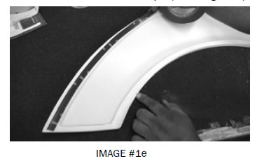
STEP 3) Make a small tail on each section of double face tape. (See Image #4d) Close the door on the car and place the door cap on the bottom of the door and align the door cap to be flush - even with the back edge of the door. The door cap should be a little short of the front edge of the door allowing the door to fully clear the side skirt when opened. Align the door cap to the top of the side skirt using the grease pencil marks previously made. Carefully pull the red backing from the tape and press the door cap - tape to the paint surface.(See Image #5d)
FENDER FLARES
HARDWARE SUPPLIED
- (4) 3M 6396 ADHESION PROMOTER
- 3M DOUBLE FACE TAPE
- (12) #8 X ¾” SELF TAPPING SCREWS
APPLYING THE 3M TAPE TO THE FENDER FLARES
After the kit has been prepped and painted, the double face tape should be applied to the parts. The tape is not pre-installed on parts prior to shipping because the tape can be contaminated during the sanding/ priming and painting process.
The first step is to clean the tape flange on the back of the parts where the tape will be applied. Make sure the complete tape flange is clean and free of all primer and paint. Using lacquer thinner on a clean rag, thoroughly clean the tape flanges on all parts of the kit.
Using the adhesion promoter bottle with felt tip supplied, apply it to the tape flanges – be careful not press too hard causing too much to be applied. The adhesion promoter will leave a thin clear polymer primer film that will increase the bonding strength of the double face tape.
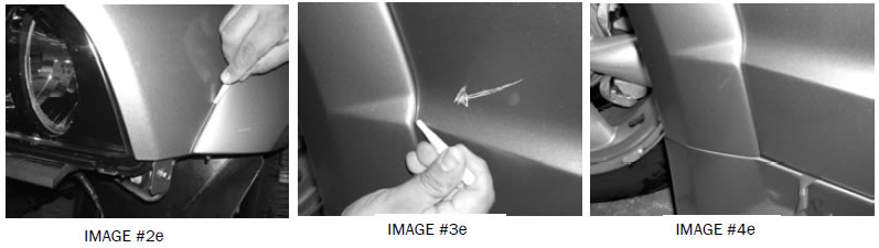
The tape should be applied 1/8” down from the top edge of the part so that it cannot be seen after the kit is installed. The tape should be applied to the flange of each part. Press the tape firmly to the surface to insure good adhesion of the double faced tape. (See Image #1e).
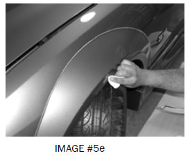
STEP 1) Place the flare on the car and check the fit. Using a grease pencil, draw a line along the top edge of the part for reference during final installation.(See Image #2e) See Image #3e as reference for where the fender flare should be positioned onto the car. After flare has been positioned and aligned with the side skirt, you can pull the rest of the plastic tape tail from the side skirt. (See Image #4e)
STEP 3) Using Lacquer thinner on a clean rag wipe the paint on the body where the double face tape will come in contact to the body. Be careful not to remove the grease pencil lines. Apply the Adhesion promoter to the paint surface where the tape will contact. (See Image #5e)
STEP 4) Make a small tail on each section of double face tape. (See Image #6e) Place the flare back on the fender and align it to the grease pencil marks previously made. (See Image 3) If necessary adjust the side skirt to the fender flare by moving the side skirt to meet the flare. After the fit is achieved secure the side skirt in the wheel well with the #8 x 3/4” self tapping screws (See Image # 6) for location. Then carefully pull the red backing from the tape and press the flare and tape to the paint surface. (See Image #7e)
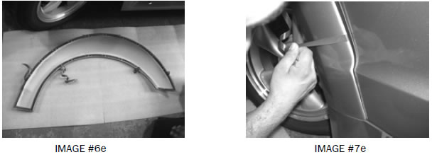
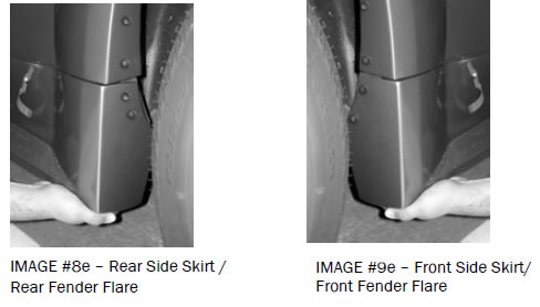
STEP 5) Secure the flare in the wheel wells with (3) #8 x 3/4” self drilling screws supplied in each wheel well. (1) screw for the front and (2) Screws for the back (See Image #8e & 9e - side skirt installation for location)
Repeat steps 1 through 5 for the all 4 flares.
Best Sellers
Related Guides
-
Installation
-
Installation
-
Installation
