 FREE 1 to 3-Day Delivery on Orders $119+ Details
Best Sellers


Accel 300+ Ignition Control System ('84-'95) - Installation Instructions
Installation Time
2 hours
Tools Required
- Small jewelers size flat blade screwdriver.
- #1 Phillips head screwdriver
- Pliers
- 1/2" Socket wrench and socket
- 7/16" Socket wrench and socket
- 1/4" Socket wrench and socket
- Power drill and drill bit for # 10 sheet metal screws
- Small wire cutters.
Installation
Instructions:
1. Look over the kit contents and read through the instructions carefully. Take note that page 4 has the specific instructions and a chart for setting the built-in Rev Limiter.
2. Now is the time to decide on where the Ignition Control Box will be located. Determine the mounting location of the Coil. Consider the layout of the Wiring Harness based on the location of the Ignition Control Box and Coil. The Accel to Ford TFI Harness is a group of wires inside a protective cover. It should be routed away from any heat sources, moving parts and other high-energy electrical wires
3. Remove the three screws that attach the end plate to the Control Box (the plain side, not the wire harness side). Inside you’ll see a rotary dial and 4 dip switches; use these to set the Rev Limit for your RPM. – I turned the dial to 5and put all 4 switches in “down” position, based on a limit of 5,750 RPM for 8 cylinders (according to the Accel chart).
4. Page 4 of the Instructions gives detailed information and a chart on how to adjust the Rev Limiter to your desired RPM. – I chose to set the Rev Limit at 5,750 RPM because that is just about where ‘red-line’ is on the factory tach. When finished, re-install the side plate using the original three screws.
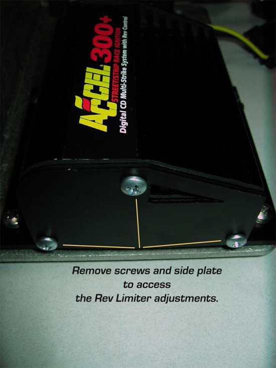
Fig2a
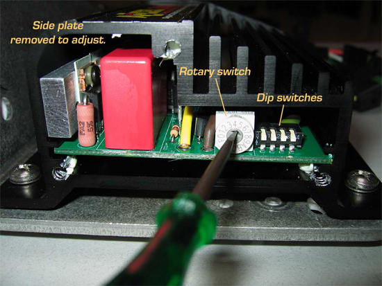
Fig2b
5. Note:I used a mounting plate in this installation that was left over from a different project and is not included as part of the Accel 300 Ignition Kit. This plate is not required to complete this installation; it is just an accessory I chose to use. See Fig1c below.
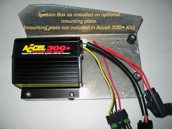
Fig1c
6. Park on a level spot, set the hand brake, pop the hood and take the keys out of the ignition. Open the hood and set the prop rod securely. Using the 1/2” socket (or appropriate size),disconnect the negative battery cable from the battery.
7. Remove the plastic coil/solenoid cover by loosening the screws that hold it in place. (See: Fig3a) Disconnect the factory TFI harness from the coil and gently move it aside. Remove the coil primary wire from the coil tower, leaving the other end connected to the distributor cap. Using the 1/4” socket, remove the 4 screws located in the corners of the coil and lift the coil from the mounting bracket.
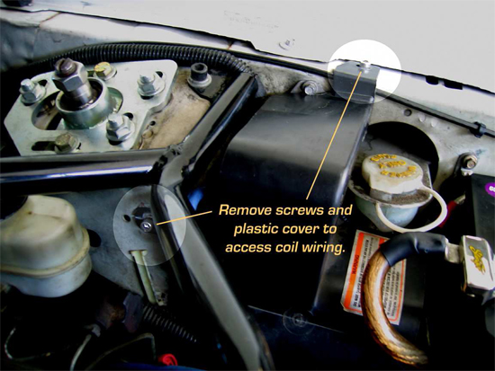
Fig3a
8. If you are going to relocate the new coil, remove the bracket and mount it in its new place. – I chose to use the stock mounting location for the Accel Coil, so I left the bracket in place. (See: Fig4a)
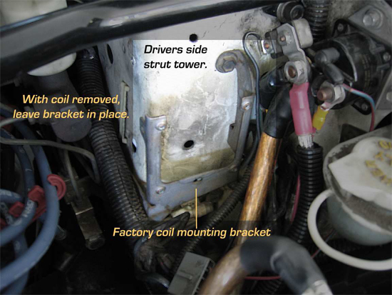
Fig 4a
9. Using the supplied new rubber-backed washers and screws, attach the Accel Coil to the mounting bracket. Tighten the screws just snugly with the 1/4” socket. – I used the rubber-backed washers between the bracket and coil to reduce vibrations getting to the coil. Do not over-tighten these little screws or you risk stripping out the bracket holes. With the new coil in place (See: Fig5a below), move to the mounting location of the Ignition Control Box.
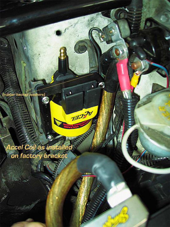
Fig5a
10. Position the box at the desired location then, using the mounting flange holes as a guide, mark the location of the mounting holes. Center punch and drill out the mounting holes to accept the Phillips head screws. Using the Phillips screwdriver, the provided screws and washers, screw the Accel Control Box securely into place. – I chose the area as seen in Fig6a and Fig7a with the end plate still accessible for any later Rev Limiter changes.
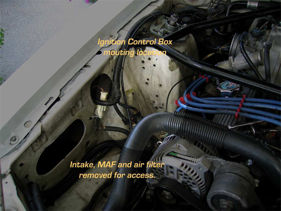
Fig6a
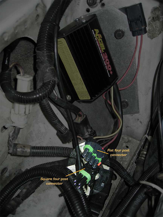
Fig7a
11. Locate the 2 installed four post connectors (one is square- the other is flat). (See:Fig7a) Use small wire cutters to snip off the tie-wrap and un-coil the Accel to Ford TFI Wiring Harness.
12. Connect the Control box to the Wiring Harness by matching the connectors, square to square and flat to flat. (See: Fig7a above and Fig7b, Fig7c below).
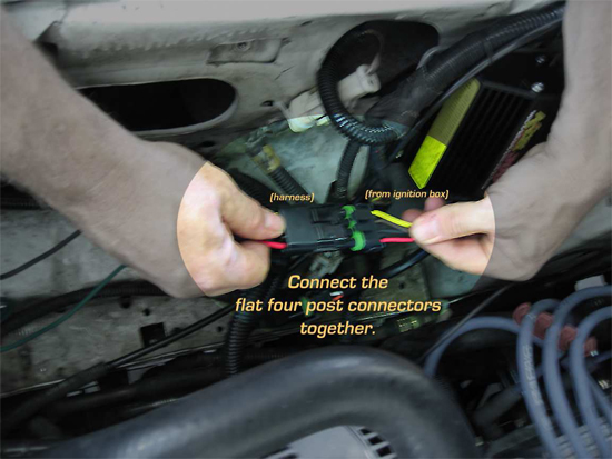
Fig7b
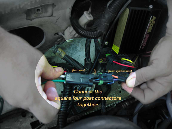
Fig7c
13. Locate the black colored ground wire coming out of the Control Box, it has large serrated ring terminal on the end. Select a clean, paint-free, rust-free, bare metal spot on the chassis to attach the negative ground wire or drill a new hole and use the supplied screws to attach the wire. – I used one of the many existing holes and a supplied screw from the kit.
14. The green wire coming from the Control Box is for an aftermarket tach, if equipped. – My car does not have another tach, so I coiled this wire up and tucked it away for future use. (See: Fig7d)
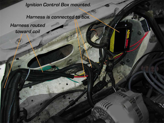
Fig7d
15. With the Harness fully connected to the Ignition Control Box, route the harness toward the Coil location. It is important to position the harness away from any heat sources, moving parts and high-energy wires. – I ran the harness over the radiator support, then over to the stock coil location. It was more than long enough to reach without any modifications or extensions (which is a BIG help!). (See: Fig8a) Remember to leave some ‘slack’ in the harness to allow for movement, the harness should not be pulled or stretched tight.
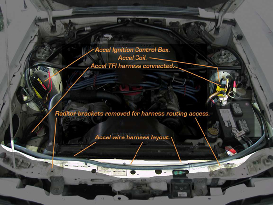
Fig8a
16. Connect the Accel TFI adapter to the Ford factory ignition connector (we moved it aside in step 4). These are ‘keyed’ one-way connectors which help to eliminate wiring mix-ups. (See: Fig8b) The remaining connector gets plugged into the Accel coil. Again, the keyed connector makes this easy. Double check that all the connectors are completely snapped together firmly.
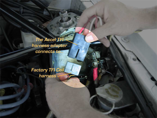
Fig8b
17. Confirm that the Ignition Control Box has a solid negative ground. Re-attach the coil primary wire to the tower on the Accel coil. Some dielectric grease on the wire boot will help seal out moisture. Securely position the wiring harness with the supplied zip-ties.
18. Replace anything that was moved or removed during the installation. – Like radiator supports, the air intake, MAF, filter, etc.
19. Finally, attach the negative battery cable to the battery. At this point if you hear any noises, see or smell smoke immediately disconnect the negative battery cable. Then investigate the cause. If not, then proceed.
20. Remove all tools and loose parts from the engine compartment area. – Look again just to be sure. (See: Fig9a)
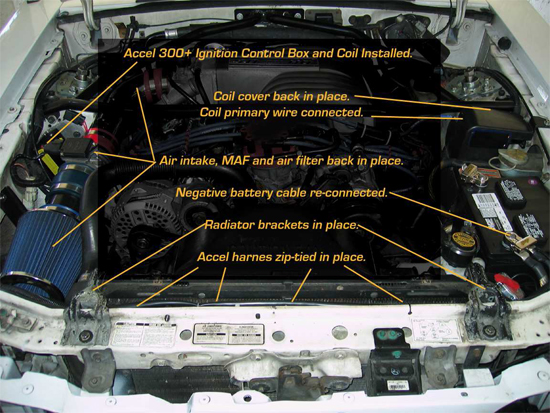
Fig9a
21. The black wire from the One Touch Top Module is for use with a light bar, allowing the third brake light to be disabled when the top is up. This wire is a ground wire, so the wire doesn’t need a wire nut. However, I went ahead and placed one on it for the future when a light bar is added. That way I already have the wire nut handy.
22. Take a deep breath, and then…Start the engine. – My engine was a bit rough for a minute or two at first, but then after the factory EEC-IV settled-in the idle smoothed right out. I understand that the EEC-IV may need some time to‘learn’ what the new Control Box is doing and recover from being disconnected.
23. Turn off the car, put the tools away, wash up and now it's time to go for a test drive! Right away I noticed a big improvement in throttle response.
Installation instructions provided by AmericanMuscle customer Curt Calfee 9.22.09
