FREE 1 to 3-Day Delivery on Orders $119+ Details
Best Sellers


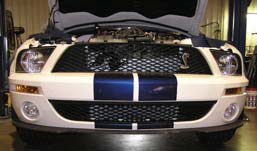
How to install a AFCO Pro-Series Heat Exchanger w/ Fans on your Mustang
Shop Parts in this Guide
Installation
Removal of Factory Unit
WARNING:
1. Radiator fluid must be handled properly. Please observe local ordinances with regards to handling and disposal.
2. Allow vehicle and components to cool a minimum of 1 hour before handling.
3. Never attempt to open the radiator cap when hot.
4. Do not allow any tools or limbs to contact fans—SERIOUS INJURY MAY RESULT.
5. Always follow directions and disconnect the battery before attempting installation.
6. AFCO is not responsible for personal injury or damage to vehicle resulting from improper installation of this product.
7. Due to vehicle variations / tolerances it is ultimately up to the installer to determine proper installation.
1. Remove the 8 clips that retain the upper radiator cowl. Remove the cowl.
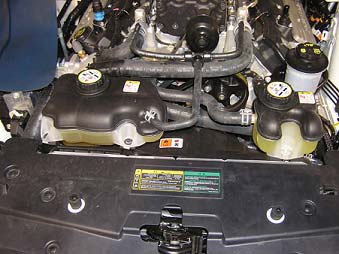
2. Remove the coolant tank cap from the heat exchanger coolant tank.
Front Bumper Cover Removal
3. Remove the two front wheels and set aside.
4. Remove the 7 screws from the lower splash guard using a 5.5mm socket and remove the splash guard.
5. Remove the 6 screws that hold the lower lip air dam to the inner fender splash guards. Then, remove the 10 bolts that hold the lip to the bumper using a 10mm socket. Remove the air dam.

6. Remove the 10 screws and clips from the fender well splash guards. Pull the splash guards back from the front bumper and remove completely.
7. Remove the two nuts that retain the front bumper to the front fender on each side. These nuts are located at the very back corners of the bumper and are accessible from inside the fender wells.
8. Unclip the three electrical connectors on each side that attach to the fog lights, turn signals, and parking lamps.
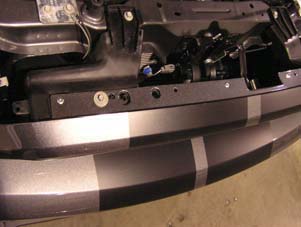
9. Remove two bolts retaining the top of the bumper to the core support.
10. Lift the top “ears” of the bumper up and over the tabs. Then, slide the whole bumper cover forward and off of the vehicle.
11. Grab the foam bumper core and pull straight out to free the 4 plastic clips. Be careful not to damage the clips or the foam core.
Heat Exchanger Removal
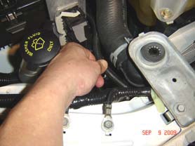
12. Drain the coolant from the heat exchanger by removing the lower hose on the passenger side of the stock unit.
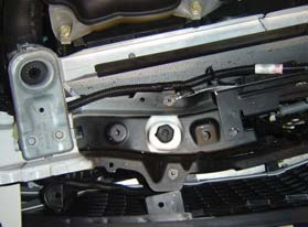
13. Remove the 4 nuts that secure the heat exchanger mount to the vehicle’s frame.
14. From above, unclip the electrical connector at the factory pump attached to the heat exchanger.
15. Unclamp and remove the hose connecting the pump to the surge tank.
16. Remove the 4 plastic clips attaching the plastic shroud to the heat exchanger.
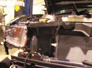
17. It is recommended at this point that the horns be removed from the vehicle to allow ease of removal of the heat exchanger without damage to the AC condenser.
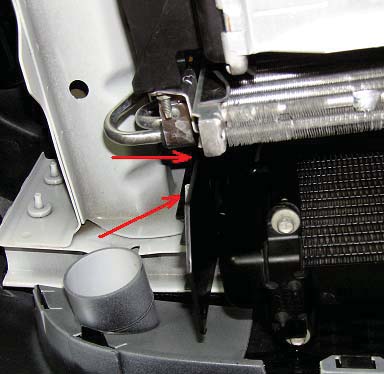
18. Using a 13mm deep well socket, remove the two bolts closest to center on each side that attach the front bumper to the frame.
19. At this point, the factory heat exchanger and bracket can be lifted up and out of the vehicle.
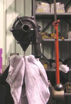
20. Remove the pump from the factory bracket and remove any hoses connected to it.
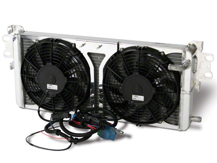
AFCO Heat Exchanger Installation
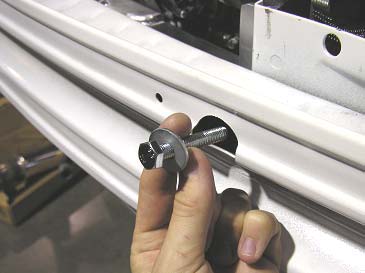
21. Install the four supplied 8mm x 50mm long bolts and washers in place of the bolts removed in step 18. Screw them in until they protrude about 1/4” from the opposite side.
22. Attach the two fans to the heat exchanger using the 8 supplied washers and button head bolts with a 1/8” allen wrench, locating the wire leads towards the bottom.
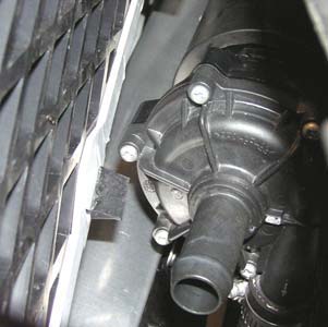
23. Using a ½” wrench, attach the stock pump in the same orientation as stock to the AFCO heat exchanger using the supplied nuts.
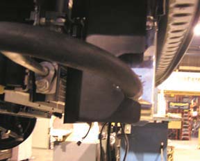
24. Connect the supplied 90o rubber hose between the pump outlet (facing down) and the heat exchanger inlet (30o tube). Trimming of the hose may be required. Clamp both ends with the supplied hose clamps.
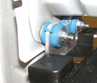
25. Snap the four supplied mounting grommets, washer side toward rear of vehicle, into the mounting holes on the heat exchanger brackets.
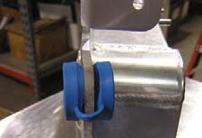
26. Slide one of the supplied aluminum bushings into each blue grommet.
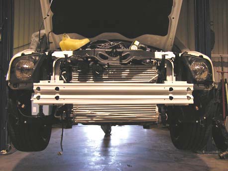
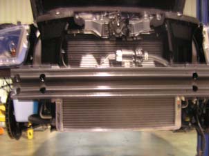
27. Slide the heat exchanger up from the bottom and place on the mounting studs.
28. If the pump outlet or hose is too close to the AC condenser or grille, rotate the pump in its rubber hanger until sufficient clearance is obtained. Lubrication of the rubber piece may be required in order to rotate or move the pump.
29. Finish threading the bolts installed in step 22 completely into the bumper and tighten. Make sure that the washers do not get caught on the lip inside of the bumper and that they are resting flat.
30. Secure the heat exchanger using the four supplied Nylock nuts. The blue grommets should crush approximately 1/16”. Do not over tighten the nuts.
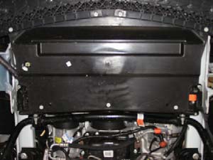
31. Install the plastic shroud on the outside of the AFCO brackets using the four factory clips.
32. Re-attach the factory hoses to the lower heat exchanger outlet and the pump inlet using the factory clamps.
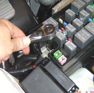
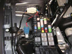
33. Remove the cover from the fuse panel and unbolt the power lead shown below.
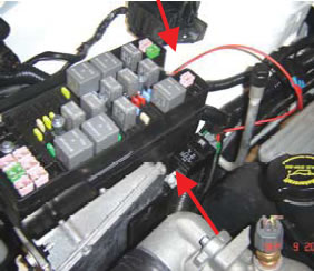
34. Place the red wire from the fan harness on top of the power lead previously removed and bolt back into place. Remove the bolt next to the fuse box and mount the relay as shown.
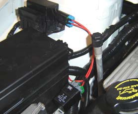
35. Mount the in-line fuse to the strut tower using the preexisting bolt. The cover should be reinstalled onto the fuse panel
36. Run the wiring harness along the engine side of the fuse box up to the passenger side of the radiator. The harness will then go through the radiator support by the horns.

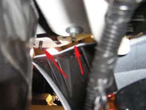
37. The ground cables should be connected to the bolt on the front support, which is shown below. The weatherpack connectors can be connected to the fans at this point.
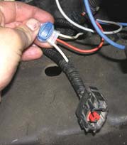
38. Remove the plastic loom on the coolant pump harness and locate the white wire. This wire will have battery voltage when the pump is activated. Cut this wire approximately 2” from the pump connector.
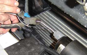
39. Insert the two ends of the wire cut in the previous step into the blue/clear 3M Scotchlock 3- way splice connector supplied. Note: It is not necessary to strip the wires, and the order of the wires inserted does not matter. Once the button is depressed, the connector is difficult to reuse, so be sure the wires are inserted completely. Insert the orange wire from the fan harness into the remaining hole. Using slip joint pliers, (or similar tool) press the blue button down into the connector until the button locks. The connector is filled with EG-3 sealant. Just wipe off any excess with a rag. You may wrap the connection with electrical tape, although it is not necessary.

40. Reconnect the electrical connector to the pump. Secure the wire-loom to the upper hose on the heat exchanger using the supplied wire ties.
41. Verify all bolts, nuts, and hose connections.
42. Fill the system and surge tank using the recommended OEM coolant.
43. Reconnect the negative battery cable, start the vehicle, and allow the car to idle until warm. The heat exchanger pump will not turn on until the air charge is warm.
44. Once the pump turns on, the level in the surge tank will drop rapidly. Continue adding coolant until at the recommended level. This system will hold approximately 1.5 gallons of coolant.
45. Continue to run the vehicle for 5 minutes to verify all air is purged from the system. Check system for leaks while waiting.
46. Once system is checked, install the bumper, splashguards, air dam, and wheels in the reverse of removal.
WARNING:
Radiator fluid must be handled properly. Please observe local ordinances with regards to handling and disposal.
Allow vehicle and components to cool a minimum of 1 hour before handling.
Never attempt to open the radiator cap when hot.
Do not allow any tools or limbs to contact fans—SERIOUS INJURY MAY RESULT.
Always follow directions and disconnect the battery before attempting installation.
AFCO is not responsible for personal injury or damage to vehicle resulting from improper installation of this product.
Due to vehicle variations / tolerances it is ultimately up to the installer to determine proper installation.
1. Remove the 8 clips that retain the upper radiator cowl. Remove the cowl.

2. Remove the coolant tank cap from the heat exchanger coolant tank.
Front Bumper Cover Removal
3. Remove the two front wheels and set aside.
4. Remove the 5 screws from the back of the lower splashguard using a 5.5mm socket.
5. Next, remove the 6 screws that hold the lower lip air dam to the inner fender splashguards. Then, remove the 10 bolts that hold the lip to the bumper using a 10mm socket. Remove the air dam and splashguard.
6. Remove the 10 clips from the fender well splash guards. Pull the splashguards back from the front bumper and remove completely.
7. Unclip the three electrical connectors on each side that attach to the fog lights, turn signals, and parking lamps. Also, unclip the horn relay from the front bumper.
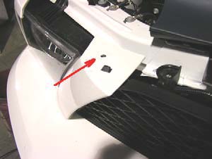
8. Grab the corners of the bumper next to the wheel well and pull outward to unsnap the two clips retaining the bumper.
9. Remove the two bolts retaining the top of the bumper to the core support.
10. Lift the top of the bumper up and over the tabs. Then, slide the whole bumper cover forward and off of the vehicle.
11. Grab the foam bumper core and pull straight out to free the 4 plastic clips. Be careful not to damage the clips or the foam core.
Heat Exchanger Removal
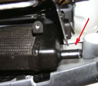
12. Drain the coolant from the heat exchanger by removing the lower hose on the passenger side of the stock unit.

13. From above, unclip the electrical connector at the factory pump attached to the heat exchanger.
14. Unclamp and remove the hose connecting the pump to the surge tank.
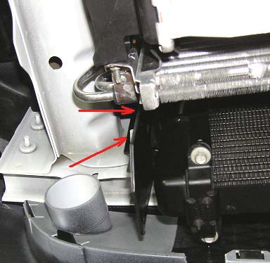
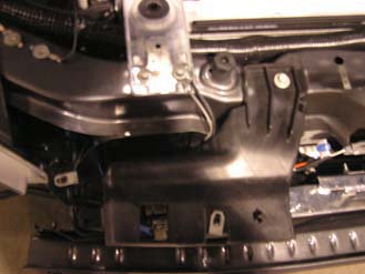
15. emove the 2 bolts and 3 snaps that hold the plastic grill mount and radiator duct. Remove these components.
16. Remove the 4 nuts that secure the heat exchanger mount to the vehicle’s frame.
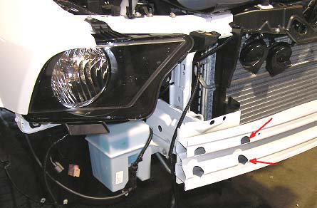
17. Using a 13mm deep well socket, remove the two bolts closest to center on each side that attach the front bumper to the frame.
18. At this point the factory heat exchanger and bracket can be lifted up to unclip the bracket, and then lowered down out of the car.
19. Remove the pump from the factory bracket and remove any hoses connected to it.
20. It is now recommended that the intake be removed to allow access to remove the hose that runs from the surge tank to the pump. Remove the one bolt holding the air filter housing, the band clamp holding the intake at the throttle body, and unplug the 2 sensors in the intake. Now remove the hose from the surge tank. The nylon sheath that protects the hose should be removed from the hose. This nylon sheath should be placed over the supplied hose, and the hose should be routed the same as factory. Attach using the supplied hose clamps.
AFCO Heat Exchanger Installation
21. Install the four supplied 8mm x 50mm long bolts and washers in place of the bolts removed in step17. Screw them in until they protrude about 1/4” from the opposite side.
22. Attach the two fans to the heat exchanger using the 8 supplied washers and button head bolts with an 1/8” allen wrench, locating the wire leads towards the bottom.
23. Using a 1/2” wrench, attach the stock pump in the same orientation as stock to the AFCO heat exchanger using the supplied spacers and nuts. Placing the mount in a vise and twisting the pump may be required to provide proper clearance. Lubrication of the rubber mount will aid in this process.
24. Connect the supplied 90o rubber hose between the pump outlet (facing down) and the heat exchanger inlet (30o tube). Trimming of the hose may be required. Clamp both ends with the supplied hose clamps.
25. Snap the four supplied mounting grommets, washer side toward rear of vehicle, into the mounting holes on the heat exchanger brackets.

26. Slide one of the supplied aluminum bushings into each blue grommet.
27. Slide the heat exchanger up from the bottom and place on the mounting studs.
28. Finish threading the bolts installed in step 21completely into the bumper and tighten. Make sure that the washers do not get caught on the lip inside of the bumper and that they are resting flat.
29. Secure the heat exchanger using the four supplied Nylock nuts. The blue grommets should crush approximately 1/16”. Do not over tighten the nuts.
30. Reinstall the plastic grille mount and radiator duct. The plastic duct will have to be trimmed slightly to allow room for the lower tube.
31. Re-attach the factory hose to the lower heat exchanger outlet, and attach the pump inlet hose, trim to fit if needed, to the pump.
Wiring the Fan Harness Kit
32. Remove the cover from the fuse panel and unbolt the power lead shown below.
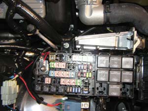
33. Place the red wire from the fan harness on top of the power lead previously removed and bolt back into place. Remove the bolt next to the fuse box and mount the relay as shown below.
34. Mount the in-line fuse to the strut tower, behind the connector, using the preexisting bolt hole and the supplied bolt. This can be seen above. The cover should be reinstalled onto the fuse panel.
35. Run the wiring harness along the engine side of the fuse box up to the passenger side of the radiator. The harness will then go through the radiator support by the grille mount.
36. The ground cables should be connected to the bolt on the radiator support, which is shown below. The weatherpack connectors can be connected to the fans at this point.
37. Remove the plastic loom on the coolant pump harness and locate the white wire. This wire will have battery voltage when the pump is activated. Cut this wire approximately 2” from the pump connector.

38. Insert the two ends of the wire cut in the previous step into the blue/clear 3M Scotchlock 3-way splice connector supplied. Note: It is not necessary to strip the wires, and the order of the wires inserted does not matter. Once the button is depressed, the connector is difficult to reuse, so be sure the wires are inserted completely. Insert the orange wire from the fan harness into the remaining hole. Using slip joint pliers, (or similar tool) press the blue button down into the connector until the button locks. The connector is filled with EG-3 sealant. Just wipe off any excess with a rag. You may wrap the connection with electrical tape, although it is not necessary.
39. Reconnect the electrical connector to the pump. Secure the wire-loom to the upper hose on the heat exchanger using the supplied wire ties.
40. Verify all bolts, nuts, and hose connections.
41. Fill the system and surge tank using the recommended OEM coolant.
42. Reconnect the negative battery cable, start the vehicle, and allow the car to idle until warm. The heat exchanger pump will not turn on until the air charge is warm.
43. Once the pump turns on, the level in the surge tank will drop rapidly. Continue adding coolant until at the recommended level. This system will hold approximately 1.5 gallons of coolant.
44. Continue to run the vehicle for 5 minutes to verify all air is purged from the system. Check system for leaks while waiting.
45. Once system is checked, install the bumper, splashguards, air dam, and wheels in the reverse of removal.