 FREE 1 to 3-Day Delivery on Orders $119+ Details
Best Sellers


How to Install Air Lift Performance 3P Pressure Adjustable Air Suspension System on your Mustang
NOTE
Air fitting and leader hose to be installed with thread sealant and torqued 1-3/4 turns beyond finger tight.
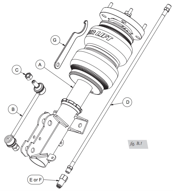
HARDWARE LIST
| Item | Part # | Description | Qty |
|---|---|---|---|
| A | 35224 | Strut - S197 Track Pack Front | 2 |
| B | 26978-010 | End Link 185mm | 2 |
| C | 26978-011 | M12 X 1.75 Nyloc Nut | 4 |
| D | 20997 | Leader Hose, 1/4” ID | 2 |
| E | 21810 | UN-1/4” FNPT-1/4” PTC “DOT” | 2 |
| F | 21987 | UN-1/4” FNPT-3/8” PTC “DOT” | 2 |
| G | 26978-012 | Collar Wrench | 1 |
Installing the Air Suspension
PREPARING THE VEHICLE
1. Elevate and support the vehicle with a hoist or jack stands.
2. Remove the front wheel and support the hub assembly.
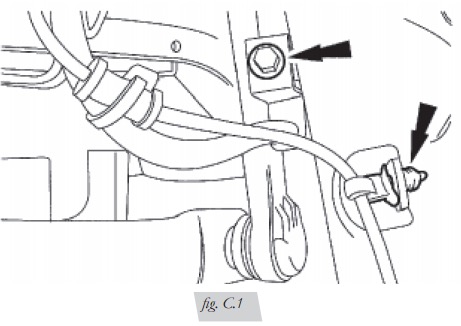
STOCK SUSPENSION REMOVAL
1. Remove the bolt from the brake line tab and release brake line from the strut (Fig. C.1).
2. Unclip the sensor wire from the strut (Fig. C.1).
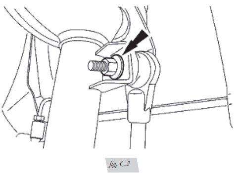
3. Unthread the stabilizer link nut from the strut and free the linkage from the strut (Fig. C.2).
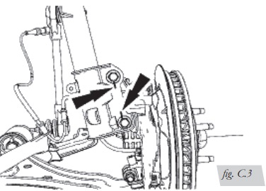
4. Support the hub assembly, unthread the spindle nuts and remove spindle bolts from
the strut assembly (Fig. C.3).
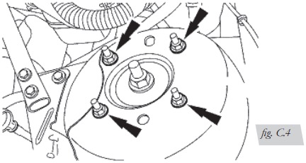
5. Under the hood, unscrew the upper mount from the vehicle chassis (Fig. C.4).
Remove strut from vehicle.
INSTALLING THE KIT COMPONENTS
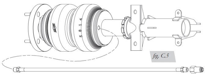
1. Begin by installing the leader hose into the air spring. Apply thread sealant to the
threads of the leader hose. Tighten the appropriate fitting to the airline (1 3/4 turns
beyond hand-tight). Tighten the leader hose into the air spring 1 3/4 turns beyond
hand-tight. (Fig. C.5).
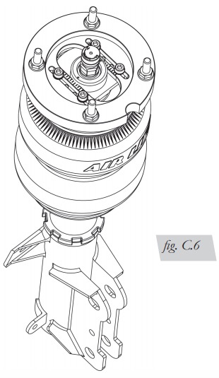
2. Insert the strut assembly into the spring pocket with the notch facing outboard.
Thread the supplied nuts onto the upper mount studs. Torque to 35Nm (26 lb-ft)
3. Align and reinstall the lower spindle bolts. Torque to 201Nm (148 lb-ft)
4. Reinstall the stabilizer link. Torque to 115 Nm (85 lb-ft)
5. Press the ABS support into the tab on the strut.
6. Using the supplied bolt and nut, reinstall the brake line. Torque to 14Nm (10 lb-ft)
7. Reinstall wheels. Torque to 133Nm (98 lb-ft)
ROUTING THE AIR LINES
1. Fully compress the suspension using a jack. With the suspension compressed,
review the best routing for the leader hose that is clear of all suspension and
steering components.
2. Routing should also allow for the suspension to extend and steer without
kinking, pulling the line tight or rubbing on other components. Following the
brake line routing is often a good place to start. Check clearances to all other
components.
Before Operating
SETTING THE RIDE HEIGHT
1. With the suspension fully compressed, take a measurement from the fender to a
chosen reference point – typically the center of the axle. Record this measurement as
max compression (MC).
2. Cycle the suspension to max extension (ME) and record the measurement from the
fender to the same reference point.
3. Add ME and MC, then divide the total by 2. Set the suspension to this point. This
position will give 50% stroke in either direction and is a starting point for ride height.
(Fig. D.1)

4. With the suspension at this position, loosen, then re-torque the lower control arm
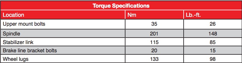
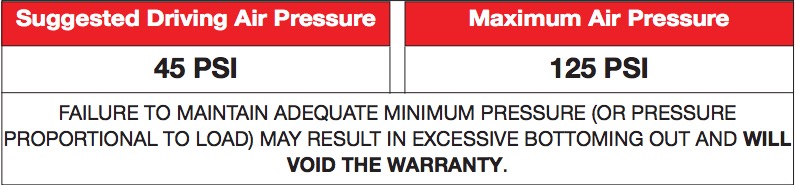
bolts to manufacturer’s specifications (Table 1):
CHECK FOR BINDING
1. Inflate and deflate the system (do not exceed 125 PSI) to check for clearance or
binding issues. With the air springs deflated, check clearances on everything so as
not to pinch brake lines, vent tubes, etc. Clear lines if necessary.
2. Inflate the air springs to 75-90 PSI and check all connections for leaks.
3. Please continue by reading the Product Use, Maintenance and Servicing section.
DAMPING ADJUSTMENT
Suspension damping is a matter compromise. Setting it too stiff will make the ride feel
jarring. In addition, if the suspension is too stiff, the tires will lose contact with the road,
reducing control and power delivery. Conversely, if the suspension is too soft, the car
can experience brake dive and excessive bouncing. The sweet spot lies somewhere in
the middle. Air Lift dampers have a range of adjustment, which allows the driver to
tune the ride and handling to his or her preferences.
Air Lift recommends damper and air pressure settings for every vehicle kit, but it is
impossible to consider every situation. For example, even though Air Lift kits replace
the dampers and springs, vehicles with sport-tuned suspensions might have stiffer
bushings, larger anti-roll bars, bigger wheels, wider tires, etc. So these settings may
need to be adjusted to different vehicles and driving characteristics.
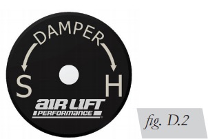
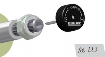
1. The dampers in this kit have 30 settings, or “clicks,” of adjustable compression and
rebound damping characteristics. Damping is changed through the damper rod using
the supplied adjuster (Figs. D.2 & D.3) or an M3 hex key (not included).
2. Turn the adjuster clockwise (H) and the damping settings are stiffened, reducing
oscillations and body motion. Turn the adjuster counterclockwise (S) and the
damping is softened.
3. Each damper in this kit is preset to “-16 clicks.” This means that the damper is
adjusted 16 clicks away from full stiff, which starts at 0. Counting up from full stiff
is the preferred method of keeping track of, or setting, damping. This setting was
developed on a 2005 Ford Mustang GT.
ALIGNING THE VEHICLE
1. Set the vehicle to the height at which it will most often be driven.
2. If the ride height is lower than stock, Air Lift recommends loosening all pivot points
(bolts, nuts) on any control arm, strut arm or radius rod that contains bushings. Once
they have been loosened, re-torque to stock specifications (Table 1).
ADJUSTING EXTENDED OR DROP HEIGHT
USING LOWER MOUNT
These dampers have been pre-set at the factory to provide maximum drop height
while maintaining adequate tire clearance to the air spring. If you wish to gain more
extended height (lift), which is the same as reducing drop height, or want to lower the
chassis further and there is still adjustment available at the lower mount, please use
the following procedure:
1. Support the vehicle with jack stands or a hoist at approved lifting points.
2. Remove the wheel.
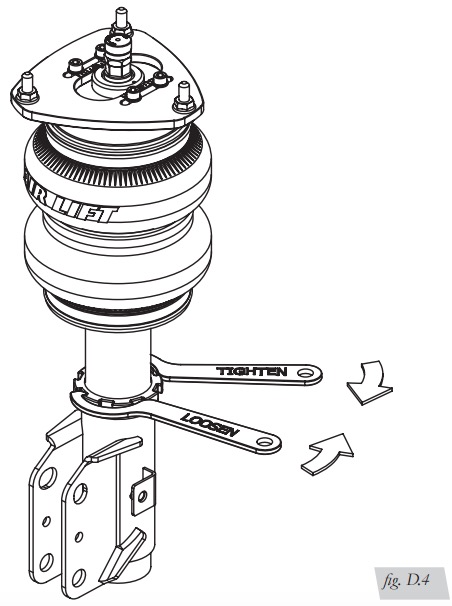
3. Using the supplied spanner wrench, loosen the locking collar. (Fig. D.4)
4. Deflate the air spring to 0 PSI on the corner you are adjusting.
5. Disconnect lower mount from suspension.
6. Spin the lower mount to the desired location.
Not all models will have further drop height available.
7. Re-install lower mount to suspension and torque fasteners.
8. Tighten the lower locking collar to the lower mount using significant force.
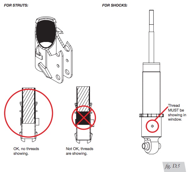
WHEN ADJUSTING HEIGHT UPWARD, MAKE SURE THAT THE DAMPER BODY ENGAGES ALL THE THREADS OF THE LOWER MOUNT (FIG. D.5). WHEN ADJUSTING DOWNWARD, MAKE SURE THERE IS ADEQUATE AIR SPRING CLEARANCE TO THE TIRE/WHEEL ASSEMBLY. CLEARANCE MUST BE CHECKED WITH SYSTEM FULLY DEFLATED AS WELL AS FULLY INFLATED TO ENSURE THAT NO RUBBING OCCURS.
FAILURE TO MAINTAIN ADEQUATE CLEARANCE CAN RESULT IN AIR SPRING FAILURE AND WILL NOT BE COVERED UNDER WARRANTY.
DO NOT ADJUST HEIGHT BY SPINNING AIR SPRING ON DAMPER! DOING SO MAY CAUSE AN AIR LEAK AND COMPROMISE THE ASSEMBLY.
INSTALLATION CHECKLIST
- Clearance — Inflate the air springs to 75-90 PSI and make sure there is at least 1/2” clearance from anything that might rub against the air spring. This should be checked with the air spring fully inflated and fully deflated.
- Leak — Inflate the air springs to 75-90 PSI and check all connections for leaks. All leaks must be eliminated before the vehicle is road tested.
- Heat — Be sure there is sufficient clearance from heat sources, at least 6” for air springs and air lines. If a heat shield was included in the kit, install it. If there is no heat shield, but one is required, call Air Lift customer service at (800) 248-0892.
- Fastener — Recheck all bolts for proper torque.
- Road — Inflate the springs to recommended driving pressures. Drive the vehicle 10 miles and recheck for clearance, loose fasteners and air leaks.
- Operating instructions — If professionally installed, the installer should review the operating instructions with the owner. Be sure to provide the owner with all paperwork that came with the kit.
POST-INSTALLATION CHECKLIST
- Overnight leak down test — Recheck air pressure 24 hours after installation and driving of the vehicle. If the pressure has dropped more than 5 PSI, there is a leak that must be fixed.
- Air pressure requirements — It is important to understand the air pressure requirements of the air spring system. Regardless of load, the air pressure should always be adjusted to maintain adequate ride height at all times while driving.
- Thirty-day or 500-mile test —Recheck the air spring system after 30 days or 500 miles, whichever comes first. If any part shows signs of rubbing or abrasion, the source should be identified and moved, if possible. If it is not possible to relocate the cause of the abrasion, the air spring may need to be remounted. If professionally installed, the installer should be consulted. Check all fasteners for tightness.
Use, Maintenance and Servicing
1. An Air Lift air management system is strongly recommended for this product, but it
is possible to operate without one. The air lines can be routed to Schrader valves for
use with a separate air compressor. Air lines and Schrader valves are not included
with Air Lift Performance kits and would need to be purchased separately. To learn
more Air Lift management systems visit air-lift.co/productlines.
2. Check the air pressure before driving.
SHOULD IT BECOME NECESSARY TO RAISE THE VEHICLE BY THE FRAME, MAKE SURE THE CONTROL SYSTEM IS TURNED OFF BEFORE LIFTING.
TUNING THE AIR PRESSURE
Pressure determination comes down to three things — level vehicle, ride comfort and stability.
1. Level vehicle
Depending on load, it is possible one side will need more pressure than the other to
level the vehicle.
2. Ride comfort
If the vehicle has a harsh ride, it may be due to either too much pressure or not
enough causing frequent bottoming. Also, riding the vehicle at the top, or close to
the top of the available stroke will cause a very uncomfortable ride due to a lack of
rebound travel. This situation should be avoided for driving any significant distance.
Try different pressures to determine the best ride comfort. See Air Lift suggested
driving air pressure for this vehicle.
3. Stability
Stability translates into safety and should be the priority, meaning the driver may
need to sacrifice a perfectly level and comfortable ride. Stability issues include roll
control, bounce, dive during braking and sponginess. Tuning out these problems
usually requires additional air pressure, damping or both.
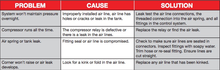
Troubleshooting Guide
TIPS FOR INSTALLING AIR LINES
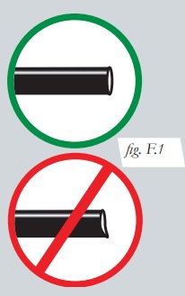
When cutting air lines, use a sharp knife or a hose cutter and make clean, square cuts (Fig. F.1). Do not use scissors or wire cutters because these tools will deform the air line, causing it to leak around fittings.
Do not cut the lines at an angle. Do not bend the 1/4” hose at a radius of less than 1” and do not put side load pressure on fitting. The hose should be straight beyond the fitting for 1” before bending.
Inspect hose for scratches that run lengthwise on hose prior to installation. Contact Air Lift customer service at (800) 248-0892 if the air line is damaged. To watch a video demonstrating proper air line cutting, go to air-lift.co/cuttingairline
CHECKING FOR LEAKS
1. Inflate the air spring to at least 80 PSI.
2. Spray all connections with a solution of 1/5 liquid dish soap and 4/5 water. Spot leaks easily by looking for bubbles in the soapy water.
3. Check the air pressure again after 24 hours. A 2-4 PSI loss after initial installation is normal. Retest for leaks if the loss is more than 5 PSI.
FIXING LEAKS
1. Air line to PTC fitting: Try pushing the air line firmly into the fitting to ensure it is properly seated. If leak persists, deflate the spring and remove the air line by pushing the collar toward the fitting body and pulling firmly on the air line. Trim 1” off the end of the air line making sure the cut is clean and square. Reinsert air line firmly into fitting and pull back on the air line to make sure it is seated.
2. Threaded connection: If possible, tighten the fitting another half turn. If the leak persists, deflate spring, remove fitting and re-coat threads with thread sealant. Reinstall to hand tight and then use wrench to finish tightening an additional 1 3/4 turns.
3. Air spring o-ring seal: If a leak is found at the upper or lower air spring seal on a strut or shock, contact Air Lift customer service at (800) 248-0892.
