 FREE 1 to 3-Day Delivery on Orders $119+ Details
Best Sellers


How to Install Air Lift Performance V2 Autopilot Digital Air Suspension System on your Ford Mustang
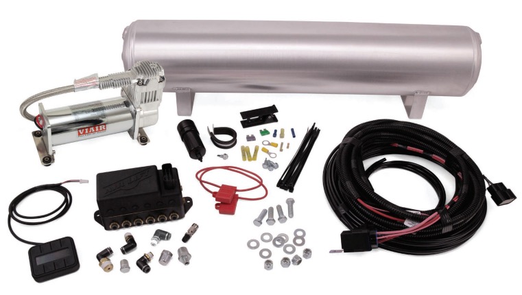
| Part # | Description | Qty |
|---|---|---|
| 72605 | 4pt Fast Air Manifold - 1/4” | 1 |
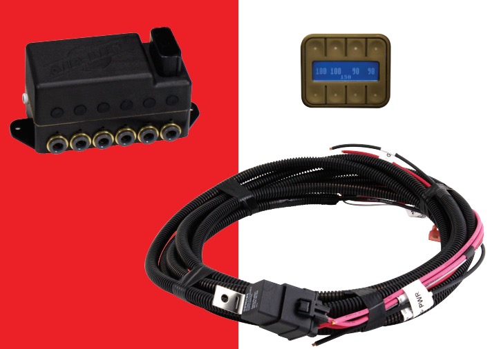
| 27042 | Gen 3 Display | 1 |
| 26498-002 | Electrical Harness - FastAir | 1 |
| 24672 | Fuse, spade 3 amp | 1 |
| 24547 | Fuse, spade, 30 amp | 1 |
| 24500 | ATC Fuse holder w/ cap | 2 |
| 24645 | 16GA Butt Connector | 1 |
| 24752 | 12-10GA Butt Connector | 3 |
| 24748 | 12GA Ring Terminal 3/8” | 2 |
| 24524 | Female Spade Terminal | 1 |
| 24595 | 12GA Female Spade Terminal | 1 |
| 24561 | Adaptor, Mini Fuse | 1 |
| 24542 | ATC/ATO Fuse Adaptor | 1 |
| 21043 | 1/4” MNPT X 1/4” PTC Elbow | 1 |
| 21847 | 3/8” MNPT X 1/4” PTC Elbow | 1 |
| 21737 | 3/8” Pipe Plug | 1 |
| 21773 | 3/8” MNPT X 1/8” MNPT Adapter | 1 |
| 21999 | 1/8” MNPT X 1/4” PTC Elbow | 2 |
| 21633 | Push Lock Valve | 1 |
| 21585 | 1/4” Pipe Plug | 1 |
| 20937 | Polyurethane Filter Drain Hose | 5ft |
| 20946 | DOT 1/4” Air Line | 60ft |
| 17263 | 1/4-14 x 1 Self Tapping Screw | 3 |
| 18444 | 3/8” Flat Washer | 8 |
| 17188 | 3/8-16 x 1.25 Hex Cap Screw | 4 |
| 18435 | 3/8-16 Nylon Lock Nut | 4 |
| 11517 | Miniature Filter | 1 |
| 11217 | P Clamp | 1 |
| 17173 | 1/4”-14 X 3/4” Self Tapping Screw | 1 |
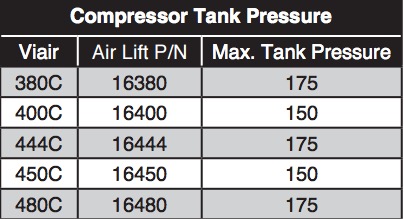
| 16444 | VIAIR 444C Compressor (200 psi) | 1 |
| 11955 | 4 Gallon Aluminum Air Tank | 1 |
| 10466 | 8” Zip Tie | 10 |
| 10530 | Air Line Cutter | 1 |
INSTALLATION GUIDE
For maximum effectiveness and safety, please read these instructions completely before proceeding with installation.
Introduction
The purpose of this publication is to assist with the installation, operation and troubleshooting of the AutoPilot V2 kit.
It is important to read and understand the entire installation guide before beginning installation or performing any maintenance, service or repair. The information includes step-by-step installation information, installation templates and a troubleshooting guide.
Air Lift Company reserves the right to make changes and improvements to its products and publications at any time. For the latest version of this manual, contact Air Lift Performance at (800) 248-0892 or visit our website at www.airliftperformance.com.
NOTATION EXPLANATION
Hazard notations appear in various locations in this publication. Information which is highlighted by one of these notations must be observed to help minimize risk of personal injury or possible improper installation which may render the vehicle unsafe. Notes are used to help emphasize areas of procedural importance and provide helpful suggestions. The following definitions explain the use of these notations as they appear throughout this guide.
DANGER - INDICATES IMMEDIATE HAZARDS WHICH WILL RESULT IN SEVERE PERSONAL INJURY OR DEATH.
WARNING - INDICATES HAZARDS OR UNSAFE PRACTICES WHICH COULD RESULT IN SEVERE PERSONAL INJURY OR DEATH.
CAUTION - INDICATES HAZARDS OR UNSAFE PRACTICES WHICH COULD RESULT IN DAMAGE TO THE MACHINE OR MINOR PERSONAL INJURY.
NOTE - Indicates a procedure, practice or hint which is important to highlight
Installing the AutoPilot V2 Kit
INSTALL COMPONENTS
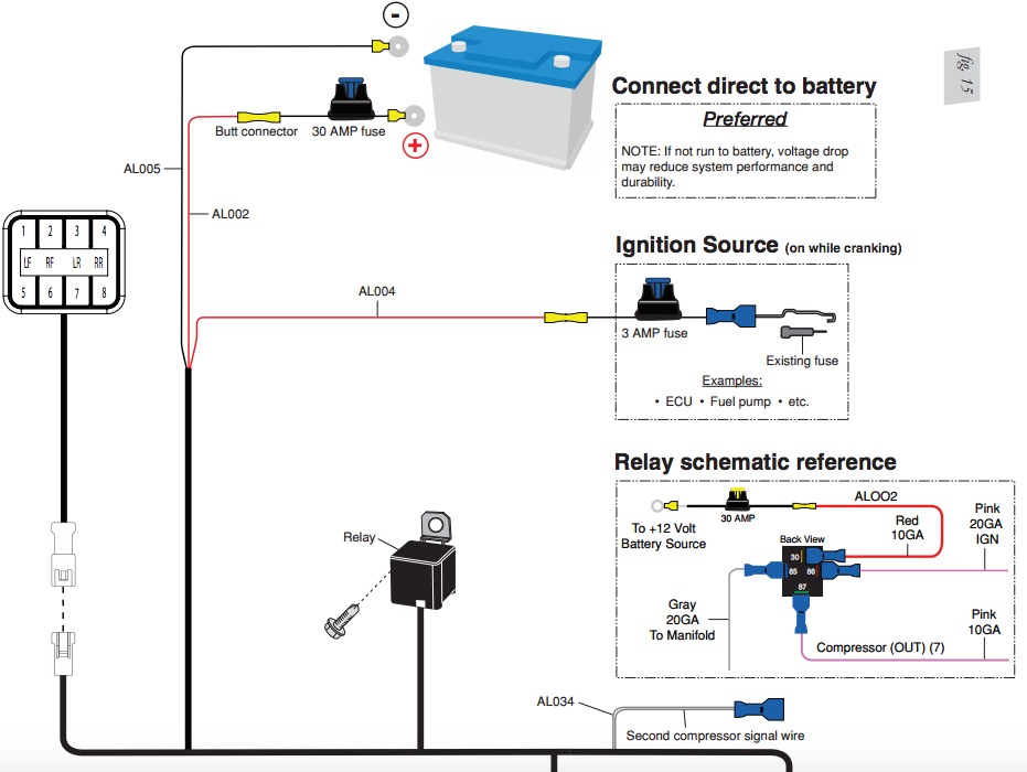
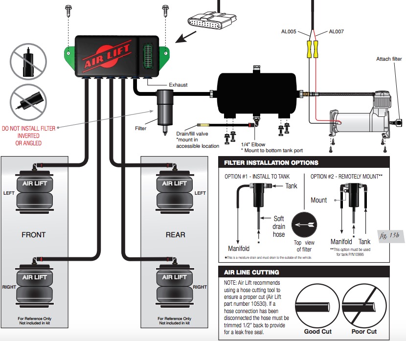
NOTE - For a complete schematic, please see fig. 15. (pages 10-11)
CAUTION - BEST PRACTICE IS TO LOCATE THE MANIFOLD UNIT INSIDE THE VEHICLE. IF EXTERNAL MOUNTING IS DESIRED, THE MANIFOLD MUST BE LOCATED IN AN AREA SHIELDED FROM DIRECT WATER SPRAY FROM TIRES OR CAR WASHES. THE MANIFOLD SHOULD BE CONSIDERED “WATER RESISTANT” NOT “WATERPROOF”
Layout
1. Plan component location first. Ideally, the manifold should be located above the compressor and tank if possible to avoid compressor ingested water from gathering in the manifold. This is most important for vehicles operated in below freezing climates.
2. Prior to mounting components, check to make sure:
• the electrical harness connections will reach the manifold and compressor.
• the compressor leader hose will reach the tank.
• the air lines will route cleanly through the vehicle without kinking or bending
NOTE - Be sure to install all components as far as possible from any heat sources. Plan and prepare harness and air line routing thru the vehicle. Eliminate all sharp edges that could chafe. Use grommets when passing through compartment walls.
Prepare and install the compressor
1. Prepare the compressor intake. If the compressor body is mounted inside the vehicle, attach filter to port on end of compressor (fig. 15). If compressor is located outside the vehicle, snorkel inlet filter to dry location inside vehicle using components supplied with compressor.
2. Center punch and drill four holes using the template on page 19.
3. Attach using the hardware supplied with the compressor.
NOTE - If the harness must be lengthened, use properly sized butt connectors and wire. If extending the power/ground wires, use 8AWG wire minimum or contact Air Lift for more information.
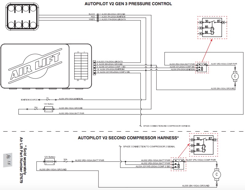
The supplied harness is only capable of powering a single compressor. If installing dual compressors, a second dedicated power wire is required. Consult the Electrical Schematic section for proper wiring, and contact Air Lift for an optional second compressor harness (part number: 27679).
Manifold
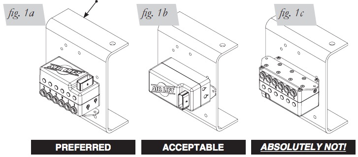
1. Position the manifold in a desired location. Make sure the manifold mounting surface is flat.
NOTE - Mount the manifold to the body either horizontally (fig. 1a) or vertically with the ports facing toward the ground (fig. 1b). Do not mount the manifold upside down (fig. 1c). Proper manifold mounting will help prevent water from settling in areas sensitive to freezing.
2. Fasten the manifold using the two self-tapping screws. If the mounting surface is not flat, add washers to space the manifold up over surface irregularities.
3. If needed, a manifold mounting template can be found on page 17.
This represents the top of the vehicle frame or any custom setup (and is the same for figures 1b and 1c).
NOTE - Air compressors intake moisture (humidity) from the outside air and will deposit water in the air tank. The AutoPilot V2 system includes a filter that will greatly reduce the potential for moisture to enter the manifold, however, tanks must be regularly purged to eliminate the possibility of water entering the manifold. Be sure to provide easy access to tank drain/fill valve (preferably outside the vehicle). This is an automatic draining filter and does not need servicing. If you find this filter to be plugged, it will need to be replaced. If using an engine-driven compressor, the life of the provided filter may be reduced due to the increased potential for oil being introduced into the system.
Tank pre-assembly (see fig. 15)
1. Per the diagram on pages 10 and 11, install the filter to the tank with supplied fittings/ adapters or remotely mount the filter using the supplied fittings, P-clamp and self tapping screw. Be sure to mount the filter in the correct orientation.
NOTE - This is a one-way filter. The arrow at the top should be pointing in the direction of the air flow from the tank to the manifold (fig. 15b).
This is an automatic draining filter that does not require servicing. If you find this filter to be plugged, it will need to be replaced. The tank will need to be purged periodically to reduce/ eliminate the potential of moisture entering the manifold.
Tank install (see fig. 15)
1. Using the tank feet as a template, drill holes for hardware assembly.
2. Attach the tank using the supplied hardware.
3. Cut an appropriate length of hose from the manifold port T, to the PTC fitting on the filter.
4. Route the drain/fill air line with a schrader valve (preferably outside the vehicle).
5. Install the supplied drain tube (soft hose) to the bottom of the filter and route to a location outside of the vehicle.
NOTE - When cutting plastic air line, only use a standard hose cutter like (Air Lift part number 10530) or razor blade. Cut all hose ends square and as smoothly as possible. See hose cutting tips on page 6.
INSTALL HARNESS
1. Disconnect the battery ground while installing the system.
2. Compressor / manifold connections (see fig. 15)
• Attach the manifold connector, it will “click” into place once fully seated.
• Mount the compressor relay in a preferred location using a self-tapping screw.
• Cut off the spade and eyelet from the compressor power and ground wires.
• Strip 1/4” of wire casing from the compressor wires.
• Strip 1/4” of wire casing from the black and pink harness wires
NOTE - Use an appropriate terminal crimp tool to ensure a good connection.
• Using a butt connector attach the RED compressor wire to the PINK harness wire.
• Using a butt connector attach the BLACK compressor wire to the BLACK harness wire.
• Carefully apply heat (preferably with a heat gun) to seal these connections.
3. Battery / ignition connections (see fig. 15)
• Identify the power, ground, ignition leg of the harness.
• Ground: 10AWG black wire; Power: 10AWG red wire; Ignition: 18AWG pink wire.
• Route power and ground leg of the harness free from any heat source to the battery. • Using a butt connector attach the red wire to a fuse holder.
• Attach an 3/8” eyelet to the other end of the fuse holder and attach to the positive battery ( ) terminal.
• Attach an 3/8” eyelet to the black wire and attach to the battery ground.
• Route the 18AWG pink wire to a key switched IGNITION source that remains on during cranking. Examples include: ECU, fuel pump.
NOTE - Do not select an accessory source. If the AutoPilot V2 display shuts off while starting the vehicle, this is not a true ignition source.
• Using a butt connector attach the pink ignition wire to a fuse holder.
• Select ignition source and attach the fused ignition wire.
• Use fuse adaptors as necessary.
4. Display
• Route the display cable as desired to the preferred operating location.
• Attach the display cable to the main harness cable (small white 3 cavity connector).
5. Reconnect the battery.
INSTALL AIR LINES
NOTE - Use a standard hose cutter (Air Lift part number 10530) or razor blade. Cut all hose ends square and as smoothly as possible.
1. Route and attach the air lines to the air springs.
• Route air lines free from abrasive edges and heat sources.
2. Attach manifold port FL to the front, drivers side left spring.
3. Attach manifold port FR to the front, passengers side right spring.
4. Attach manifold port RL to the rear, drivers side left spring.
5. Attach manifold port RR to the rear, passengers side right spring.
6. Attach manifold port T to the PTC fitting previously installed on the filter.
7. Manifold port E is the exhaust port.
• Port E can be left open, or routed to a preferred exhaust location
NOTE - Air lines should be pushed in firmly, with a slight back and forth rotational twist – check the connection by pulling on each line to verify a robust connection.
Release the air line from the fitting by releasing air, pushing on the line, depressing the ring towards the fitting, and then pulling the hose out of the fitting.
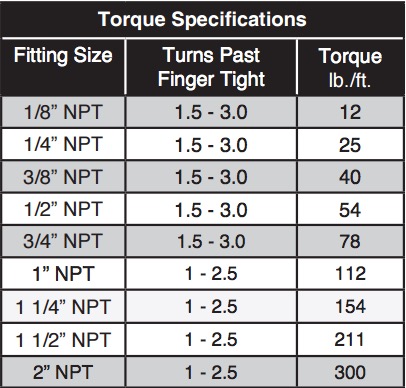
NPT ASSEMBLY INSTRUCTIONS
1. Inspect the port and fitting ensuring both are free of contaminants and excessive burrs and nicks.
2. Apply a stripe of liquid pipe sealant around the male threads leaving the first two threads uncovered.
3. Screw finger tight into the port.
4. Wrench tighten the fitting to the correct turns past finger tight position (see table 1 located on page 6).
CAUTION - NEVER BACK OFF AN INSTALLED PIPE FITTING TO ACHIEVE PROPER ALIGNMENT. LOOSENING INSTALLED PIPE FITTINGS WILL CORRUPT THE SEAL AND CONTRIBUTE TO LEAKAGE AND FAILURE.
Table 1
HELPFUL TIPS: AIR LINE AND FITTINGS
1. Minimum hose bend radius
• 3/8” hose = 1.5” hose bend radius.
• 1/4” hose = 1” hose bend radius.
2. Hose to fitting
• No side loading on fitting from hose.
• Hose straight for 1” before bending.
3. Hose cutting
• Cut hose perpendicular to hose length.
• Inspect hose for scratches that run lengthwise on hose prior to insertion.
• Use proper hose cutter, or razor on flat surface.
4. DOT/SAEJ844 air brake hose data
• Maximum working pressure of 175 PSI.
• Not to be used for frame (body) to un-sprung mass connection, use a braided leader hose for this moving connection
Table 2
Setup and Calibration
AutoPilot V2 is an advanced pressure-based air suspension control system, that uses stateof-the-art software algorithms to calibrate or map the control system to your vehicle. Once the system is calibrated, the algorithm predicts required “valve open time” to move the air suspension to achieve preset target pressures. AutoPilot V2 has 8 programmable presets, allowing the user to input 8 different combinations of the 4 corner air spring pressures.
After installing AutoPilot V2 in your vehicle, please follow the steps below to properly set up your new system. If changes are made after installing and calibrating the system such as changes to air springs, lines, tank, compressor, or other vehicle modifications, the system must be recalibrated to maintain accuracy.
SYSTEM CALIBRATION AND SETTINGS
1. Key-on/power up, and compressor should come on to fill the tank. Check to make sure system is triggered by IGNITION source. While starting the engine, the system should be ON. If not, please refer back to the “Install Harness” section.
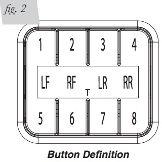
2. Press buttons 1 and 5 simultaneously (1 5) and hold for 5-10 seconds until settings and diagnostics mode main page appears (fig. 3).
Tank Adjust (Maximum System PSI)
Press button 1 (TANK ADJUST). Set tank pressure preference by pressing MAX up/ down buttons simultaneously (fig. 4). The MAX value sets compressor cut-off pressure. Press buttons (1 5) simultaneously to exit to settings and diagnostics mode.

NOTE - MIN tank pressure will follow MAX within 15 PSI to provide further accuracy.
If tank MAX settings are changed, a system recalibration is necessary for optimal performance. Max tank pressures for various compressors can be found in table 2.

Calibrate to your vehicle
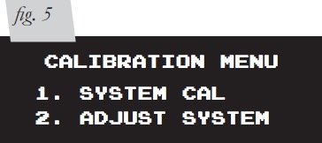
Press button 2 to enter CALIBRATE (fig. 3). Press button 1 SYSTEM CAL (fig. 5), follow instructions to calibrate AutoPilot V2 system to your vehicle. Once calibration is complete, Press buttons (1 5) simultaneously to exit to settings and diagnostics mode
CAUTION - DURING CALIBRATION THE SYSTEM WILL AUTOMATICALLY DEFLATE TO 0 PSI AND RAISE TO 100 PSI ON EACH AXLE AUTOMATICALLY. IF WHEELS EXTEND BEYOND FENDERS, VEHICLE DAMAGE MAY RESULT. CALIBRATION ON NARROW WHEELS THAT TUCK INSIDE THE FENDERS IS RECOMMENDED. ALSO, MAKE SURE VEHICLE BODYWORK WILL NOT BE HARMED IF ONE END IS RAISED TO 100 PSI AND THE OTHER IS AT ZERO. IF DAMAGE IS POSSIBLE, IT MAY BE BEST TO CALIBRATE BY SETTING VEHICLE ON BLOCKS OF WOOD (SAME HEIGHT) TO GIVE THE BODYWORK MORE CLEARANCE.
Backlight Setting
Press button 3 to enter BACKLIGHT (fig. 3). Set display backlight to your preference by pressing the and – on R (Red), G (Green), B (Blue) (fig. 6). Press buttons (1 5) simultaneously to exit to settings and diagnostics mode.

Automatic Preset Maintenance
Press button 4 (fig. 3) to enter PRESET MAINTAIN. Press button 8 to turn ON or OFF (fig. 7). When ON, this function actively monitors air spring pressure and fills to maintain active preset pressure when average pressure drops below a threshold due to a system leak.

NOTE - This function will not exhaust pressure. If air spring pressure is higher than preset target, only the operator pressing the preset button again will activate the system to exhaust air spring pressure (for safety). Press buttons (1 5) simultaneously to exit.
PRESET MAINTAIN should be off for performance/track driving or if operating in extremely hilly areas
Compressor Test / Run Time
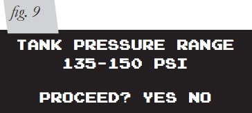
Press button 5 to run a compressor test (fig. 8). This function will exhaust the tank to the specified MIN tank pressure, then turn ON the compressor and measure its inflate time to achieve MAX pressure (fig. 9). AutoPilot V2 will record this fill time, allowing the operator to compare future fill times to determine compressor performance. Press buttons (1 5) simultaneously to exit. Press button 6 (fig. 8) to view the number of hours the compressor has been running.

Rise on Start
Press button 7 (fig. 8) to enter RISE ON START (fig. 10). This function will automatically activate valves to achieve preset 1 target pressures when the vehicle is keyed-on. This function allows the operator to drive away seconds after vehicle is started. Press buttons (1 5) simultaneously to exit.

NOTE - This function only operates when the start-up pressures are BELOW the Preset 1 target pressures. The system will not deflate to achieve Preset 1 target
Set Units (PSI / BAR)
1. Press button 8 (fig. 8) to toggle between PSI and BAR pressure units and check software version. Press buttons (1 5) simultaneously to exit.
2. Press buttons (1 5) simultaneously to exit settings and diagnostics – you are now ready to create presets.
NOTE - BAR stands for DeciBar values.
Program Presets
Program Preset 1
NOTE - Preset 1 should always be entered as the desired ride pressure for the RISE ON START function
Determine desired ride pressures: press buttons (1 5) simultaneously to toggle display to MANUAL mode. Manually activate each corner (see MANUAL mode section page 13) to achieve desired “normal driving” ride pressure (fig. 11). Program preset 1: press buttons (1 5) simultaneously to toggle display to PRESET mode (fig. 12). Press and hold button 1 for 3 seconds to set preset 1. Release button and actual air spring pressures will appear (fig. 12). Fine-tune the pressures by pressing up/down buttons. Press and hold to scroll. Press buttons (1 5) simultaneously to save and exit


Program Presets 2-8
You are now free to program the additional 7 presets to desired pressures. Typical presets can be:
• “Low”: set pressures to the lowest possible pressures for extreme low driving stance.
• “Front up”: for speed bump or driveway clearance.
• “Rear up”: for added load of passengers, equipment.
• “Play”: for those that want to enjoy their air suspension freedom, AutoPilot V2 has a special function that recognizes side-to-side presets. When left side pressures are equal, and right side pressures are equal but >25PSI different than left, the algorithm will activate side to side instead of front to back. It will also equalize all air spring pressures when exiting the “play” preset, conserving air by using the high pressure side to inflate the low pressure side. Pairing two “play” presets together allows side-to-side activation that consumes far less air than manual mode activation would consume.
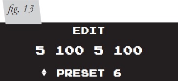
Sample Pressure Layouts for Play Mode (figs. 13 & 14)
Operating the System
Now that your system is set up, it’s time to use it. If changes are made after installing and calibrating the system such as changes to air springs, lines, tank, or compressor, the system must be recalibrated to maintain system accuracy.
There are two operational modes: PRESET and MANUAL. Pressing buttons (1 5) simultaneously will toggle between modes. After 10 seconds of non-use, the display enters standby where the LCD dims. Any button hit will “wake-up” the display and allow users to activate the system. See mode operation below for more details.
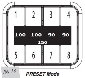
PRESET Mode
1. If display is sleeping, press any button once to “wake up” the display. If display is illuminated, go to the next step. Press of any button will display the programmed preset pressures for that button. Users can quickly view each preset prior to activating to make sure they are selecting the desired preset.
2. A 2nd button press of the same preset button within 2 seconds will activate it. The system will iterate up to 6 times to achieve the preset target pressures by /- 3 PSI. The display shows PLEASE WAIT as it iterates, then will flash SUCCESSFUL when achieved or UNSUCCESSFUL if not able to achieve the target pressure window.
3. Micro adjust to ±1 PSI: If more accuracy is desired, double press the same preset and the system will refine pressures closer to target. This is often necessary when target preset pressures are LOWER than current pressure. Accuracy can be improved by rolling the vehicle straight while activating the preset.
NOTE - If the system indicates UNSUCCESSFUL, refer to troubleshooting guide on page 13
PRESET Mode: Improve Accuracy
If system reads SUCCESSFUL but pressures are consistently lower or higher than target, you can improve first attempt accuracy by going to Calibration Menu (fig. 5) and pressing button 2. Adjust the ADJ value to a higher number if first attempt pressures are lower than target. Adjust the value to a lower number if first attempt pressures are higher than target.
CAUTION - WHEN A PRESET IS ACTIVATED THAT LOWERS THE VEHICLE SIGNIFICANTLY BELOW DRIVING HEIGHT, BE SURE TO HAVE THE FRONT WHEELS STEERED STRAIGHT AHEAD TO AVOID FENDER TO TIRE DAMAGE.
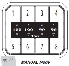
MANUAL Mode
1. MANUAL mode allows the user to fill or exhaust each spring independently. The display will show arrows above and below the pressures to indicate manual control mode (fig. 17). The arrow will be solid when the spring is filling/exhausting, and outlined when not active.
2. The system detects button press time. For a very short (<0.1sec) duration press, the system will open the valves for a defined “burst”, changing pressure minimally so users can fine-tune their pressures. For a longer than 0.1 sec duration press, the valves open as long as you hold the button down. If a button is held active, the fill/exhaust will time out after 10 seconds.
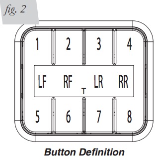
• Fill springs: buttons 1 - 4, Exhaust springs: buttons 5 - 8
Troubleshooting Guide
For further technical assistance please contact our customer service department by calling (800) 248-0892, Monday through Friday. For calls from outside the USA or Canada, dial (517) 322-2144.
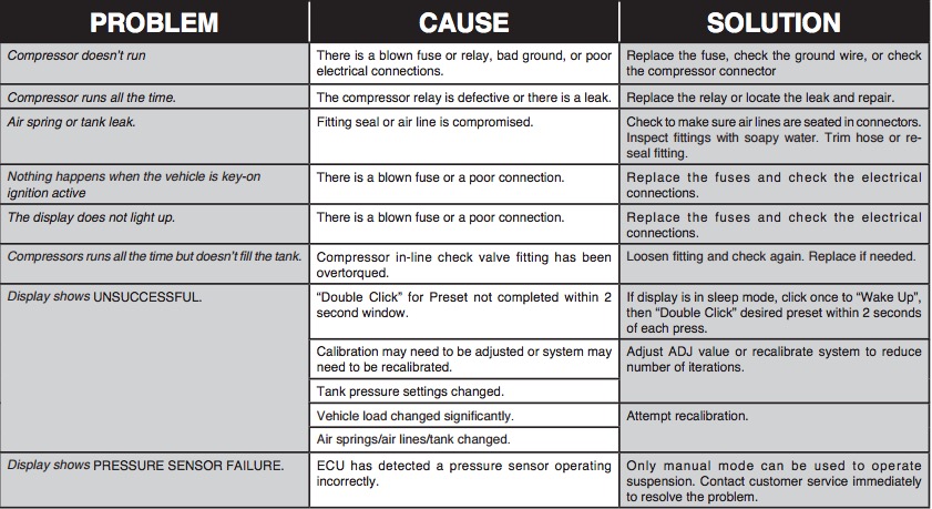
Leak Testing and Detection
Leak detection
1. A leak can be defined as a loss of pressure of more than 5 psi over an 8 hour period. Be aware that ambient temperature change has an effect on pressure that may seem like a leak. For example: a change of 10deg Fahrenheit up or down from your baseline will have an approximate gain or loss of indicated pressure of 2 psi. If a leak is suspected after including any temperature change, then proceed to #2.
2. Spray soapy water (1/5 Dawn brand dish soap to 4/5 water) on suspect fittings and hose connections and look for any bubbling caused by air leakage.
3. Fix leaking connection (review pg. 6 for help on NPT fittings and air line connections).
4. Wipe down sprayed connections with rag to remove any residual soapy water
NOTE - Dawn brand dish soap will not corrode the metals (aluminum, brass, steel) with which it comes into contact.
Electrical Schematic
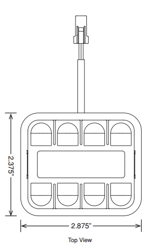
AutoPilot V2 Remote Control Unit Dimensions
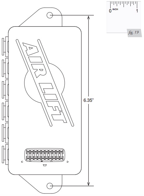
Manifold Template
CAUTION - IMPORTANT: PRINT THIS MANUAL AT 100% SCALE. THIS MANUAL CONTAINS A DRILLING TEMPLATE, WHICH WOULD BE RENDERED INCORRECT IN DIMENSION IF PRINTED WITH ANY SCALING. USING AN INCORRECT TEMPLATE TO DRILL HOLES MAY CAUSE DAMAGE TO THE VEHICLE!
PLEASE REFER TO THE ONE-INCH SCALE (FIG. 19) AND USE A MEASURING TOOL TO CONFIRM THAT THE PRINTED SCALE MEASURES ONE-INCH TO VERIFY THAT THE TEMPLATE HAS BEEN PRINTED AT 100% SCALE. IF IT IS PRINTED AT ANY SCALE OTHER THAN 100%, YOU COULD END UP DRILLING IN THE WRONG LOCATIONS ON THE VEHICLE.
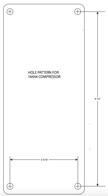
1644 Compressor Mounting Template
Limited Warranty and Return Policy
WHAT THIS WARRANTY COVERS
Air Lift Company, for all Air Lift Performance products, except its Air Lift Performance 3H™ and 3P™ systems, warrants to the original purchaser for a period of one year from the date of original purchase that the Air Lift Performance damper kits will be free from defects in workmanship and materials for the normal expected life of the part when used on cars and trucks as specified by Air Lift Company and under normal operating conditions, subject to the requirements and exclusions set forth below.
Air Lift Company provides a Limited Lifetime Warranty to the original purchaser of its Air Lift Performance 3H™ and 3P™ Control/Air Management Systems, that the Air Lift Performance products will be free from defects in workmanship and materials for the normal expected life of the part when used on cars and trucks as specified by Air Lift Company and under normal operating conditions, subject to the requirements and exclusions set forth below.
WHAT THIS WARRANTY DOES NOT COVER
The warranty does not apply to products that have been improperly applied, improperly installed, or which have not been maintained in accordance with installation instructions furnished with all products. This warranty does not apply and is void if damage or failure is caused by: accident, abuse, misuse (including but not limited to racing or off-road activities or commercial use), abnormal use, faulty installation, liquid contact, fire, earthquake or other external cause; operating the product outside Air Lift Company’s instructions, specifications or guidelines; or service, alteration, maintenance or repairs performed by anyone other than Air Lift Company to the product from its purchased condition. This warranty also does not apply to: Universal Air (Fabricator Kits), consumable parts, such as batteries; cosmetic damage, including but not limited to scratches or dents; defects caused by normal wear and tear or otherwise due to the normal aging of the product, or if any serial or identification number has been removed or defaced from the product. Air Lift Company reserves the right to change the design of any product without assuming any obligation to modify any product previously manufactured.
LIMITATION OF LIABILITY
To the extent permitted by law, this warranty and the remedies set forth herein are exclusive and in lieu of all other warranties, remedies and conditions, whether oral, written, statutory, express or implied. AIR LIFT COMPANY DISCLAIMS ALL STATUTORY AND IMPLIED WARRANTIES, INCLUDING WITHOUT LIMITATION, WARRANTIES OF MERCHANTABILITY AND FITNESS FOR A PARTICULAR PURPOSE AND WARRANTIES AGAINST HIDDEN OR LATENT DEFECTS TO THE EXTENT PERMITTED BY LAW. To the extent such warranties cannot be disclaimed, such implied warranties shall apply only for the warranty period specified above. Please note that some states do not allow limitation on how long an implied warranty (or condition) lasts. So the above limitation may not apply to you.
Except as provided in this warranty and to the extent permitted by law, Air Lift Company shall not be liable for any direct, special, incidental or consequential damages resulting from any breach of warranty or condition, or arising in connection with the sale, use or repair of air lift products, or under any other legal theory, including but not limited to loss of use, loss of revenue, loss of actual or anticipated profits, loss of the use of money, loss of business, loss of opportunity, loss of goodwill, and loss of reputation. Air Lift Company’s maximum liability shall not in any case exceed the purchase price paid by you for the Air Lift product. Please note that some states do not allow the exclusion or limitation of incidental or consequential damages, so the above limitation or exclusion may not apply to you.
HOW TO GET SERVICE
If a defect in workmanship or materials causes your Air Lift Performance product to become inoperable within the warranty period, before returning any defective product, call Air Lift Company at (800) 248-0892 in the U.S. and Canada (elsewhere, (517) 322-2144) to obtain a Returned Materials Authorization (RMA) number. The consumer shall be responsible for removing (labor charges) the defective product from the vehicle and returning it, shipping costs prepaid, to Air Lift Company for verification. Returns to Air Lift Company must be postage prepaid and sent to: Air Lift Company • 2727 Snow Road • Lansing, MI • 48917. You must prove to the satisfaction of Air Lift Company the date of original purchase of your Air Lift Performance product. You must also enclose the RMA number and a return address. A minimum $10 shipping and handling charge will apply to all warranty claims. You must also pack the product to minimize the risk of it being damaged in transit. If we receive a product in damaged condition as the result of shipping, we will notify you and you must seek a claim with the shipper.
WHAT AIR LIFT COMPANY WILL DO
If you submit a valid claim to Air Lift Company during the warranty period, Air Lift Company will, at its option, repair your Air Lift Performance product or furnish you with a new or rebuilt product. Air Lift Company will not reimburse you for repairs or replacement parts provided by other parties. Your repaired or replacement Air Lift Performance product will be returned to you (subject to payment of the required warranty claim shipping and handling charge) and it will be covered under the warranty for the balance of the warranty period, if any. When a product or part is replaced, any replacement item becomes your property and the replaced item becomes property of Air Lift Company. You are responsible for installation/reinstallation (labor charges) of the product.
HOW THE LAW RELATES TO THIS WARRANTY
This warranty gives you specific legal rights and you may also have other rights which vary from state to state. By this warranty, Air Lift Company does not limit or exclude your rights except as allowed by law. To fully understand your rights, you should consult the laws of your state.
Replacement Part Information
If replacement parts are needed, contact the local dealer or call Air Lift customer service at (800) 248-0892. Most parts are immediately available and can be shipped the same day.
Contact Air Lift Company customer service at (800) 248-0892 first if:
• Parts are missing from the kit.
• Need technical assistance on installation or operation.
• Broken or defective parts in the kit.
• Wrong parts in the kit.
• Have a warranty claim or question.
Contact the retailer where the kit was purchased:
• If it is necessary to return or exchange the kit for any reason.
• If there is a problem with shipping if shipped from the retailer.
• If there is a problem with the price.
Contact Information
Mailing address
P.O. Box 80167
Lansing, MI 48908-0167
Shipping address for returns
2727 Snow Road
Lansing, MI 48917
Phone
Toll free: (800) 248-0892
International: (517) 322-2144
Email
[email protected]
Web address
www.airliftcompany.com
Need Help?
Contact our customer service department by calling (800) 248-0892, Monday through Friday.
For calls from outside the USA or Canada, dial (517) 322-2144.
