FREE 1 to 3-Day Delivery on Orders $119+ Details
Best Sellers


How to Install Air Lift Performance 4-Way Manual Control System (1/4 in. Air Lines, 4 Gallon Tank, 3
Introduction
The purpose of this publication is to assist with the installation, maintenance and
troubleshooting of the Air Management System.
It is important to read and understand the entire installation guide before beginning installation
or performing any maintenance, service or repair. The information here includes a hardware
list, tool list, step-by-step installation information, maintenance guidelines and troubleshooting
guide.
Air Lift Company reserves the right to make changes and improvements to its products and
publications at any time. For the latest version of this manual, contact Air Lift Company at
(800) 248-0892 or visit our website at www.airliftcompany.com.
IMPORTANT SAFETY NOTICE
The installation of this kit does not alter the Gross Vehicle Weight Rating (GVWR) or payload
of the vehicle. Check your vehicle’s owner’s manual and do not exceed the maximum load
listed for your vehicle.
Gross Vehicle Weight Rating: The maximum allowable weight of the fully loaded vehicle
(including passengers and cargo). This number — along with other weight limits, as well
as tire, rim size and inflation pressure data — is shown on the vehicle’s Safety Compliance
Certification Label.
Payload: The combined, maximum allowable weight of cargo and passengers that the
vehicle is designed to carry. Payload is GVWR minus the Base Curb Weight.
NOTATION EXPLANATION
Hazard notations appear in various locations in this publication. Information which is
highlighted by one of these notations must be observed to help minimize risk of personal
injury or possible improper installation which may render the vehicle unsafe. Notes are used
to help emphasize areas of procedural importance and provide helpful suggestions. The
following definitions explain the use of these notations as they appear throughout this guide.
INDICATES IMMEDIATE HAZARDS WHICH WILL RESULT IN SEVERE PERSONAL
INJURY OR DEATH.
INDICATES HAZARDS OR UNSAFE PRACTICES WHICH COULD RESULT IN SEVERE
PERSONAL INJURY OR DEATH.
INDICATES HAZARDS OR UNSAFE PRACTICES WHICH COULD RESULT IN DAMAGE
TO THE MACHINE OR MINOR PERSONAL INJURY.
NOT ASSEMBLY INSTRUCTIONS
1. Inspect the port and fitting ensuring both are free of contaminants and excessive burrs
and nicks.
2. Apply a stripe of liquid pipe sealant around the male threads leaving the first two threads
uncovered.
3. Screw finger tight into the port.
4. Wrench tighten the fitting to the correct turns past finger tight position (see table 1).
NEVER BACK OFF AN INSTALLED PIPE FITTING TO ACHIEVE PROPER ALIGNMENT.
LOOSENING INSTALLED PIPE FITTINGS WILL CORRUPT THE SEAL AND CONTRIBUTE
TO LEAKAGE AND FAILURE.
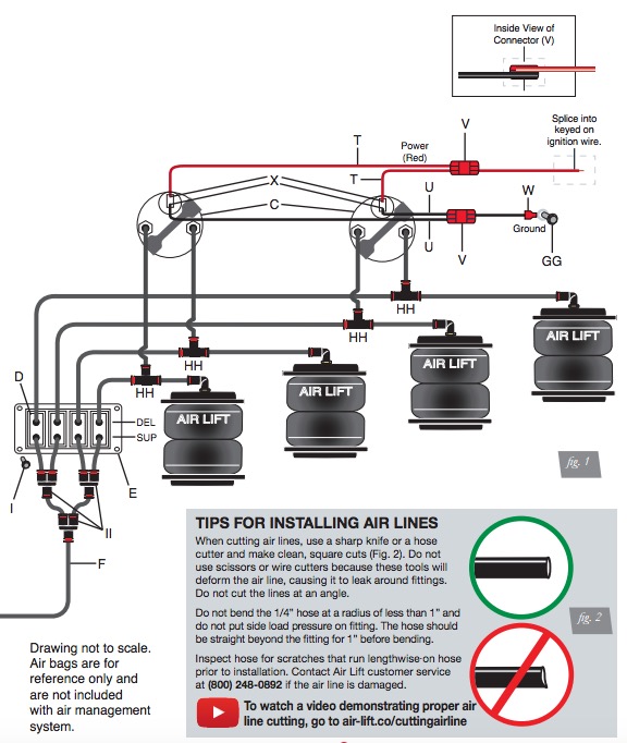
HELPFUL TIPS: AIR LINE AND FITTINGS
1. Minimum hose bend radius
• 1/4” hose = 1” hose bend radius.
2. Hose to fitting
• No side loading on fitting from hose.
• Hose straight for 1” before bending.
3. Hose cutting
• Cut hose perpendicular to hose length.
• Inspect hose for scratches that run lengthwise on hose prior to insertion.
• Use proper hose cutter, cigar cutter, or razor on flat surface.
4. DOT/SAEJ844 air brake hose data
• Maximum working pressure of 175 PSI.
• Not to be used for frame (body) to un-sprung mass connection, use a braided leader
hose for this moving connection.
Layout
1. Plan component location first.
2. Prior to mounting components, check to make sure:
• the compressor leader hose will reach the tank.
• the plumbing will route cleanly through the vehicle.
NOTE
Be sure to install all components as far as possible from any heat sources. Plan and prepare
wiring and plumbing routing through the vehicle. Eliminate all sharp edges that could chafe.
Use grommets when passing through compartment walls.
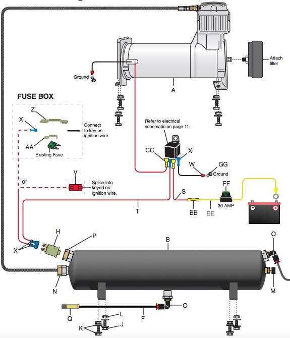
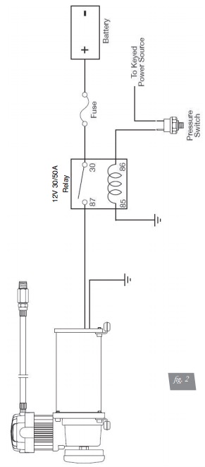
Prepare and install the compressor
1. Prepare the compressor intake. If inside the vehicle, attach filter to port on end of
compressor (fig. 1). If the compressor is located outside the vehicle, snorkel inlet filter
to a dry location inside vehicle using components supplied with the compressor.
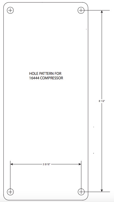
2. Center punch and drill four holes using the template on page 15.
3. Attach using the hardware supplied with the compressor.
NOTE
Air compressors ingest moisture and will deposit water in the tank. Tanks must be regularly
purged to eliminate the possibility of water freezing inside the system or causing corrosion. Be
sure to provide easy access to drain/fill valve (preferably outside the vehicle). The system does
not include moisture separators or water traps, and does require periodic tank moisture drain.
If using an engine driven compressor, proper oil and water filtration must be added as these
compressors will contaminate the air suspension system. Water traps are available and sold
separately through Air Lift Performance, part numbers: 21011 (1/4”), 21012 (3/8”), 21013 (1/2”).
Tank pre-assembly
1. Determine tank location and orientation prior to installing fittings.
2. Apply thread sealant as necessary to all fittings.
3. Install the drain/fill PTC fitting in the lower most tank threaded port.
4. Choose a tank threaded port for the compressor fitting.
5. Choose the highest tank threaded port for air line supply.
6. Plug any remaining tank ports with hex plugs.
Tank install (see fig. 1)
1. Using the tank feet as a template, drill holes for hardware assembly.
2. Attach the tank using the supplied hardware.
3. Cut an appropriate length of hose from the manifold port T, to the PTC fitting on the tank.
4. Route the drain/fill air line with a schrader valve (preferably outside the vehicle).
NOTE
When cutting plastic air line, only use a standard hose cutter like (Air Lift part number 10530)
or razorblade. Cut all hose ends square and as smoothly as possible. See hose cutting tips
on page 4.
MOUNTING THE SWITCH PANEL
Refer to the switch panel template on page 13.
1. Find a location to mount the paddle switch mounting bracket (E).
2. Snap all four paddle switches (D) into the paddle switch mounting bracket (E) so the
DEL is toward the top.
NOTE
You may select different locations for the paddle switches. The paddle switches do not need
to be used with the supplied paddle switch mounting bracket.
3. Cut six pieces of air line (F) the same length (approximately 3”-6”).
4. Push four of these pieces onto the “SUP” port of the switch. Attach two Y fittings (II) to
the air lines.
5. Push the other two pieces of line into the Y fittings (II).
6. Attach the last Y fitting (II) to the air lines.
7. Mount the paddle switch mounting bracket (E) with four screws (I).
ATTACHING THE AIR LINES
WHEN CUTTING OR TRIMMING THE AIR LINE, USE THE AIR LINE CUTTER (G). A
CLEAN, SQUARE CUT WILL ENSURE AGAINST LEAKS. DO NOT USE WIRE CUTTERS
OR SCISSORS TO CUT THE AIR LINE. THESE TOOLS MAY FLATTEN OR CRIMP THE
AIR LINE, CAUSING IT TO LEAK.
1. Run a length of air line (F) from the air fitting on the compressor to the end of the switch
cluster.
2. Run a length of air line from the remaining air fittings on the switch to its respective air
spring.
3. Repeat step 2 for the remaining air fittings and air springs.
4. Use a tee and connect into each one of the air spring lines to connect to it’s respective
gauge port.
5. Test and make sure that the switches operate the appropriate air springs.
Tuning the Air Pressure
Pressure determination comes down to three things — level vehicle, ride comfort, and
stability.
1. Level vehicle
If the vehicle’s headlights are shining into the trees or the vehicle is leaning to one side,
then it is not level. Raise the air pressure to correct either of these problems and level
the vehicle.
2. Ride comfort
If the vehicle has a rough or harsh ride it may be due to either too much pressure or
not enough. Try different pressures to determine the best ride comfort.
3. Stability
Stability translates into safety and should be the priority, meaning the driver may need
to sacrifice a perfectly level and comfortable ride. Stability issues include roll control,
bounce, dive during braking and sponginess. Tuning out these problems usually requires
an increase in pressure.
Leak Testing and Detection
Leak detection
1. A leak can be defined as a loss of pressure of more than 5 psi over an 8 hour period.
Be aware that ambient temperature change has an effect on pressure that may seem
like a leak. For example: a change of 10˚ Fahrenheit up or down from your baseline will
have an approximate gain or loss of indicated pressure of 2 psi. If a leak is suspected
after including any temperature change, then proceed to #2.
2. Spray soapy water (1/5 Dawn brand dish soap to 4/5 water) on suspect fittings and hose
connections and look for any bubbling caused by air leakage.
3. Fix leaking connection (review pages 3 and 4 for help on NPT fittings and air line
connections).
4. Wipe down sprayed connections with rag to remove any residual soapy water.
NOTE
Dawn brand dish soap will not corrode the metals (aluminum, brass, steel) with which it comes into contact.
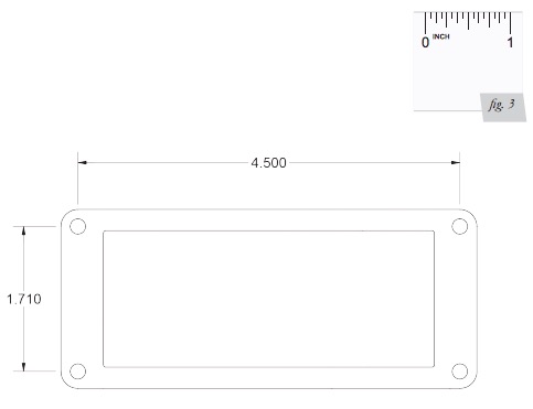
Paddle Switch Mounting Bracket Template
IMPORTANT: PRINT THIS MANUAL AT 100% SCALE. THIS MANUAL CONTAINS
DRILLING TEMPLATES, WHICH WOULD BE RENDERED INCORRECT IN
DIMENSION IF PRINTED WITH ANY SCALING. USING AN INCORRECT TEMPLATE
TO DRILL HOLES MAY CAUSE DAMAGE TO YOUR VEHICLE.
REFER TO THE ONE-INCH SCALE (FIG. 3) AND USE A MEASURING TOOL TO
CONFIRM THAT THE PRINTED SCALE MEASURES ONE INCH TO VERIFY PROPER
SCALE. IF THIS IS PRINTED AT ANY SCALE OTHER THAN 100%, THE INSTALLER
COULD END UP DRILLING IN THE WRONG LOCATIONS ON THE VEHICLE.