 FREE 1 to 3-Day Delivery on Orders $119+ Details
Best Sellers


How to Install B & M Shift Improver Kit on your Mustang
Installation Time
3 hours
Tools Required
- Oil drain pan
- 4" thin common screw driver
- 6" needle nose pliers
- 6" standard pliers
- Ford Servo removal tool T92P- 70023-A or equivalent
- 3/8" drive rachet
- 8mm & 10mm 3/8" drive socket
- 6" x 3/8" drive extension
- 8" flat file
- Petroleum jelly
Shop Parts in this Guide
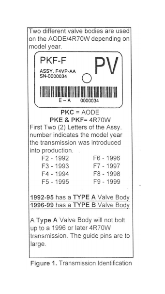
1. Make sure you have the right kit! The transmission in your vehicle may have been replaced under warranty. Replacement transmissions generally (though not always) conform to the specifications of the model year when they are installed. Check the transmission I.D. tag located on the left hand side of the case to verify the transmissions model year (See Fig. 1 ).
2. Caution: Some vehicles equipped with air bags must have the airbags disabled before hoisting or jacking up the vehicle. Consult your owner's manual for the proper hoisting or jacking procedures.
3. Please do not assume this kit will work in a later model year transmission than is indicated on the face of these instructions. Factory product development introduces component changes almost every model year. Installing this kit in a more recent model year transmission than it was designed for could lead to complete transmission failure. Please check with your B&M supplier for the current applications part numbers.
4. B&M's A0DE/4R70W Shift Improver Kit was designed to provide firm positive shift quality and improve transmission durability in original vehicle installations and those with moderate engine power improvements. This kit was not designed for and is not suitable for all out raciAg applications.
5. No recalibration kit can fix an already ailing transmission. If your A0DE/4R70W is slipping, overheating, shifting irregularly or making noise, you should repair it before or, in conjunction with the installation of this kit.
6. Installation of this kit requires Metric hand tools as well as the following special tools to remove and replace the 1-2 Accumulator assembly: Internal retaining pliers (Sears M45490 or equivalent). Ford Servo Piston Removal tool T92P- 70023-A or equivalent. An experienced transmission technician should be able to remove and reinstall the 1-2 Accumulator assembly without the aid of the Servo Piston Tool. See the tool list located at the rear of this booklet for tool requirements.
7. Caution: Replacement separator plates are NOT available for this transmission. Be very careful to use the correct drill bit size when drilling the orifices.
8.You will need approximately 10 quarts of ATF (stock pan) to refill the transmission.
GENERAL INFORMATION
Your A0DE/4R70W Transmission is controlled by the PCM (Powertrain Control Module), which has full control of it's operation. All of the parameters that control fluid pressure, shift point RPM and TCC (Torque Converter Clutch) lockup speed have been preprogrammed into the PCM at the factory. We have designed this kit as an easy way to overcome the less desirable features of the factory calibrated imperceptible shifts. The B&M A0DE/4R70W Shift Improver Kit mechanically recalibrates your transmission to produce firm positive shifts, this helps reduce clutch pack heat build up and improves transmission durability. This kit does not change or modify the shift point speed (RPM) in any range.
All transmission shift point speed (RPM) remains under control of the PCM as they are currently calibrated. With this kit you can set the shift feel characteristics of your transmission to one of two levels of shift performance, Heavy Duty or Street. Heavy Duty level produces a solid, noticeably firm shift when compared to the stock shift feel. While Street level produces a slightly quicker and more aggressive shift compared to Heavy Duty level. After installing the B&M Shift Improver Kit the actual shift feel you get will depend on the current PCM calibration, the ATF (Automatic Transmission Fluid) temperature and the type of ATF you have used. As ATF temperature increases it becomes thinner (less viscous) which allows the fluid to flow faster through small orifices thereby producing faster shift rates. In addition to the effects of temperature, each type of ATF (B&M Trick Shift®, Mercon®, Type F, etc.) has a specific characteristic friction property. This characteristic friction property is one of the variables that determines shift feel and clutch torque capacity. Mercon® type ATF's were formulated to produce smooth imperceptible shifts. While B&M Trick Shift® ATF with its higher friction properties results in firmer shift quality than Mercon® type ATF. Mercon® or B&M Trick Shift® ATF's are suitable for use in your AODE/ 4R70W transmission. For Maximum performance and positive shift feel we recommend B&M Trick Shift® ATF.
Cautions about PCM
The PCM turns ON (Illuminates) the MIL (Malfunction Indicator Light or Check Engine Light) whenever it detects a component (engine or transmission) malfunction. When the PCM turns the MIL ON it also sets a
OTC (Diagnostic Trouble Code) in the PCM's memory. You may have to
refer to your owners manual, a FORD service manual or visit a FORD dealer
to determine the source of the malfunction(s) that cause(d) any OTC codes to be set and the required remedy. When installing this kit the Ml L may be turned ON if the ignition switch is turned ON while any of the transmission electrical connectors are disconnected. So it is a good idea to disconnect the battery before starting to work on the transmission and not reconnecting it until after all work is completed. If you accidentally set the MIL you may be able to reset it (after correcting the cause) by disconnecting the battery for 15 to 20 minutes. Make sure your engine is in good tune and any problems related to set trouble codes are repaired BEFORE attempting to install your B&M kit. Before installing your B&M Shift Improver Kit there are several other B&M products you may wish to consider:
TRICK SHIFT® ATF
Trick Shift® Performance Automatic Transmission Fluid is a specially blended oil formulated with foam inhibitors, extreme pressure agents and shift improvers, this fluid assures protection while delivering the fastest possible shifts. You literally "Pour in performance". Trick Shift® ATF is available at your B&M dealer.
TRANSMISSION OIL COOLER We feel that it is very important that every vehicle used in heavy duty or high performance application should have an auxiliary oil cooler. Excessive heat is the primary cause of transmission failures, and an auxiliary oil cooler is an inexpensive safeguard against overheating and failure. B&M offer's a wide range of transmission coolers to suit every need and are available at your B&M dealer.
TEMPERATURE GAUGE KIT80212 Most transmission and converter failures can be traced directly to excessive heat. The B&M transmission temperature gauge can save you a costly repair bill by warning you of an overheated transmission. The B&M temperature gauge comes with all necessary hardware and is easy to install.
DRAIN PLUG KIT 80250 AODE/4R70W transmission oil pans are not factory equipped with drain plugs. The B&M Drain plug kit is inexpensive and easy to install. It eliminates the mess when changing fluid or on pan removal.
CAST DEEP PAN 40287 Provides approximately 4 quarts additional A TF capacity. increasing the transmissions overall cooling capacity. The B&M A0DE/4R70W Shift Improver Kit can be installed in just a few hours by carefully following the instructions. The first thing to do is select the level of shift performance desired depending on the vehicles intended use:
1. Heavy Duty Level; Towing, campers, 2 and 4-wheel drive light trucks. This level produces solid, noticeably firm shifts.
2. Street Level; Dual purpose performance vehicles. This level prcx.luces quicker, slightly more aggressive shifts than Heavy Duty Level.
Please note: The factory PCM shift calibration can vary with vehicle model and year which results in some cases that Street level may be firmer than expected. We recommend you start with the Heavy Duty performance level. If after trying the Heavy Duty level you want more aggressive shifts you can easily upgrade to Street level by performing the Street Level modifications.
INSTALLATION PRECAUTIONS Automatic transmissions normally operate at temperatures between 150F and 250F. We strongly recommend that the vehicle be allowed to cool for several hours before attempting disassembly to avoid serious burns from hot ATF and parts. The vehicle should be raised so there is at least 2 feet ground clearance for ease of installation and safety.
MAKE SURE THE VEHICLE IS RIGIDLY AND SECURELY SUPPORTED, JACK STANDS, WHEEL RAMPS OR A HOIST WORK BEST--DO NOT USE JACKS ALONE.
Transmission components are precision fit, work slowly and do not force any parts. Burrs and dirt are the number one enemies of an automatic transmission. Cleanliness is very important, so a clean work surface from which oil can easily be removed is necessary. Choose a clean, dirt and dust free place to work on your transmission. Dirt, loose threads from rags and pieces of old gaskets can become lodged in valve bores and/or separator plate orifices and cause the transmission to malfunction. If you do not have a solvent cleaning setup available, get several spray cans of WD40® to clean your parts with.
When working on the valve bodies remove and replace the items in one valve train at a time. This will minimize the chance of loosing parts, mixing them up or other errors. When finished, clean thoroughly with solvent, then check all of the valve trains for freedom of movement (use thin screw driver to move valves). Warning: Almost all cleaning solvents pose a threat of fumes and or fire. Make sure to use cleaning solvents only in a well ventilated location away from any source of ignition such as open flames, sparks, hot water heaters, clothes dryers, etc.
VERY IMPORTANT
Only use petroleum jelly to hold check balls, filter screens and gaskets in place during installation. DO NOT use any kind of heavy or stringy bearing grease to hold the check balls in place, these greases may not dissolve or mix readily with ATF and can block shift and pressure control solenoid feed circuit filters and orifices. Loss of solenoid control pressure can causing erratic shifts and potentially serious transmission damage due to low line pressure.
DISASSEMBLY
Have a large oil drain pan ready to catch oil and a clean tray on which to put small parts, check balls and bolts so they won't get lost or dirty.
Step 1. Raise and support the vehicle. Place drain pan under transmission.
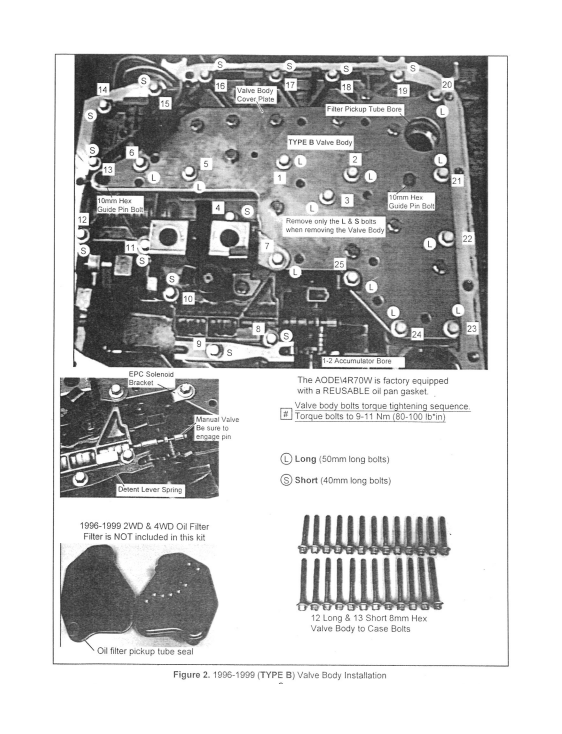
Step 2. Using a 10mm socket remove twelve (12) oil pan bolts leaving two (2) bolts at front or rear of the pan. Slowly loosen the two (2) remaining pan bolts and allow pan to tilt down and drain. Once drained remove oil pan, carefully setting the reusable pan gasket aside where it cannot get damaged. Grab the oil filter and pull it straight out of the case. Verify whether or not the filter pickup tube seal has remained stuck in the valve body bore or is in place on the pickup tube. Remove the seal from bore if it is stuck there.
Step 3. Make a sketch of the location and orientation of the connectors and wire leads on the valve body. Disconnect all electrical connectors and swing loom out of the way for removing the valve body. Most '98 and later units will have a rigid circuit assembly with latched connectors at each solenoid connection point. Carefully unlatch the circuit assembly and remove it from the valve body.
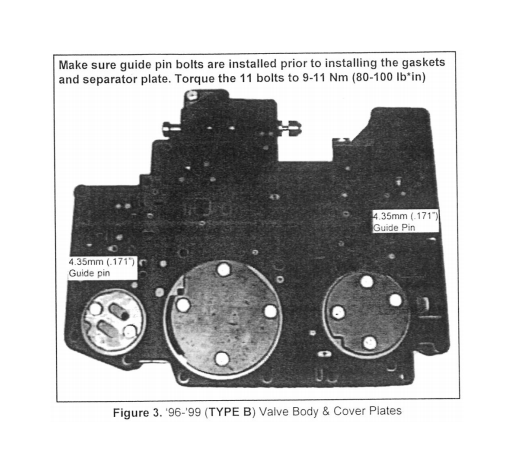
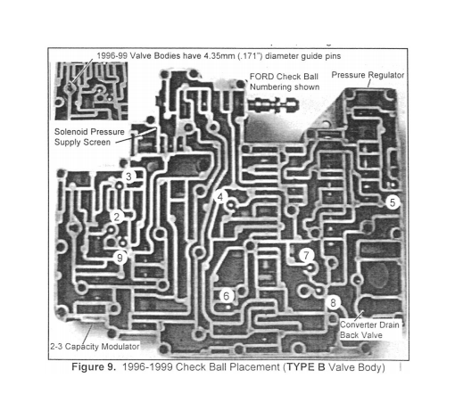
Step 4. Remove the' 25, 8mm hex head bolts holding the valve body, Detent Spring and EPC Solenoid Bracket (See Fig. 2) leaving one bolt in center of valve body until last. Do not remove the valve body reinforcement plate bolts. Holding the valve body up to the case, slowly remove the remaining bolt and lower the valve body from case. Place the valve body on a clean surface with the separator plate side facing up. Make a note of the orientation of the three round reinforcement plates (See Fig. 3). Remove the eleven (11) 8mm hex head bolts holding the three (3) round reinforcing plates and separator plate to the valve body. Carefully lift the separator plate and gaskets off the valve body. Remove Check Balls, Solenoid Pressure Supply Screen and Converter Drain Back Valve (See Fig. 9). Remove all of the old separator plate gasket material from the case, valve body and separator plate surfaces. Rinse parts with solvent.
Caution: Be extremely careful when handling and cleaning the valve body. Some of the valve train retaining plates or clips may fall out if the valve body is dropped on a hard surface or blown on with compressed air.
Step 5. Pressure regulator Spring: Using one of the short valve body bolts, depress the pressure regulator boost valve sleeve so the retaining clip can be removed. Beware; the retaining clip is spring loaded and can fly off during removal. Carefully remove the retaining clip, boost valve assembly and stock pressure regulator spring (See Fig. 4). Replace the stock spring with the VIOLET pressure regulator spring from the kit. Install the spring, boost valve assembly and retaining clip in reverse order of disassembly.
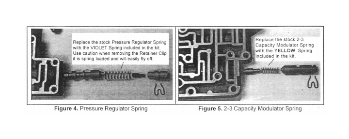
Step 6. 2-3 Capacity Modulator Spring (See Fig. 5 ): Depress the orifice control valve train sleeve and remove retaining clip. Remove orifice control valve or plug and spring. Removal of 2-3 capacity modulator valve is not required. Reinstall using the YELLOW 2-3 capacity modulator spring from the kit, orifice control valve or plug and retaining clip in reverse order of disassembly.
Caution: Replacement separator plates are NOT available for this transmission. Be very careful to use the correct drill bit size when drilling the orifices.
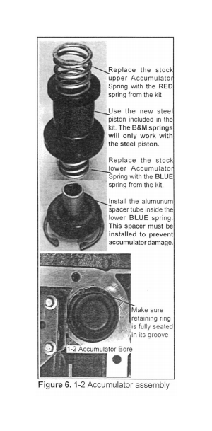
Step 7. 1-2 Accumulator: Caution: The 1-2 accumulator assembly may be spring loaded (depending on model), use caution during removal. Depress 1-2 accumulator cover (Servo Piston Removal tool may be required) and remove retaining ring from bore. Carefully relax pressure and remove the 1-2 accumulator cover, lower spring, piston and upper spring from the bore (see Fig. ). Note: Not all springs mentioned are present in all models. After removing the 1-2 accumulator piston check the condition of the case bore. If the bore is scored, sand it smooth with fine grit paper then carefully remove all abrasive contamination from the bore and case when finished. Using the new Steel 1-2 Accumulator piston supplied reassemble the 1-2 accumulator as shown (See Fig. 6).
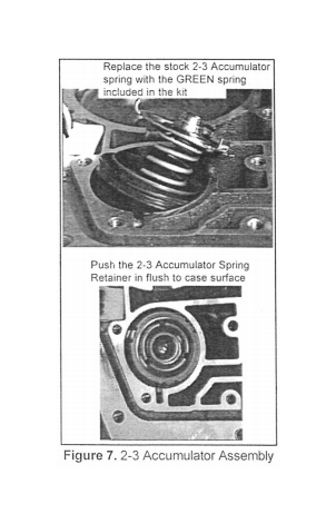
Step 8. 2-3 Accumulator: Carefully pry the 2-3 Accumulator spring retainer from its bore (See Fig. 7). Remove the stock spring and replace it with the Green 2-3 Accumulator spring from the kit and reinstall the retainer to hold it in place.
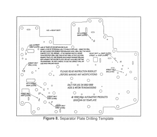
Step 9. Lay the drill guide template on top of the separator plate, holding it in place with several dabs of petroleum jelly (See Fig. 8). Using the supplied drill bits, drill only the orifices pointed to with the appropriate size drill for the performance level you desire (HD = Heavy Duty Level and Street = Street Level). When finished remove the template and deburr the orifices just drilled. Thoroughly clean the separator plate.
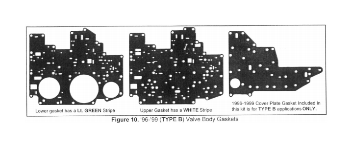
Step 10. Very Important: Place the new separator plate gaskets on the separator plate, one at a time, and check to make sure that no separator plate hole is blocked. Finally stick the gaskets in place on their appropriate sides with petroleum jelly and align all of the holes. You will notice that the gaskets will have many holes without corresponding holes in the plate, not to worry. Just make sure that no plate hole is blocked or obstructed that could prevent a clutch or lube circuit from functioning properly. Once this check has been performed stick the gaskets in place on their appropriate sides of the plate with petroleum jelly and align all of the holes. If your gaskets become torn or damaged replace them only with gaskets for the specific year and model transmission you are working on.
Step 11. ('96-'99 TYPE B ONLY) remove thirteen (13) 10mm hex head valve body cover plate bolts. Remove old gasket and replace with the new gasket from kit. Reinstall bolts and torque to 9-11 Nm (80-100 lb*in). Note: If the two (2) Guide Pin Bolt Heads (See Fig. 2) are 13mm Hex, Do Not install the kit gasket, you are working on an earlier model (TYPE A) valve body which uses a reusable cover plate gasket.
Step 12. Install all 8 Check Balls, Solenoid Pressure Supply Screen and Converter Drain Back Valve into valve body (See Fig. 9 ). Make sure the two (2) guide pin bolts are installed in the valve body. Next, place the separator plate with gaskets on the valve body and install the three (3) circular reinforcement plates and eleven (11) 8mm hex head bolts. Torque the bolts to 9-11 Nm (80-100 Inn),
Step 13. Prior to installing the valve body, double check all of the steps completed up to this point. All gaskets in place and cover plate bolts torqued? Place valve body up to case guiding the Manual Valve groove onto the manual lever pin (See Fig. 2) and the two (2) valve body alignment pins into the case. Make sure the valve body is sitting flush against the case then install twenty five (25) 8mm hex head bolts (see figure 2 for lengths) and required brackets and detent spring. After installing all bolts finger tight, torque bolts to 9-11 Nm (80-100 lb*in) starting at the center bolt and work circularly outwards (See Fig. 2). Caution; over torquing the bolts can distort the valve body and bind the shift valves. Reconnect the solenoid electrical connectors.
Step 14. Double check the installation, all bolts torqued, electrical connectors installed, EPC bracket and Detent spring installed? Make sure the old oil filter pickup tube seal has been removed from the oil filter pickup bore (See Fig. 2). Coat a new oil filter pickup tube seal with clean ATF and install the filter onto valve body. Wipe the pan gasket, case pan rail and oil pan rail surfaces clean. Place pan and gasket up to case and install fourteen (14) 10mm hex head bolts. Torque all pan bolts to 12-15 Nm (9-11 lb*ft). Avoid leaks, Do not over tighten the pan bolts.
Step 15. Fill transmission with approximately 9.5 quarts (stock pan) ATF. For maximum performance, Street level applications we recommend B&M Trickshift0ATF. When fluid can be seen on the dipstick, the engine can be started.
First place the selector lever in Park or Neutral, hold the brakes firmly then start and idle the engine. Shift the transmission a dozen or so times repeatedly from Reverse to Drive to circulate fluid through the valve body. Place the selector lever in Neutral and then top off the fluid level to the appropriate mark on the dipstick. Turn engine off.
Step 16. Lower the vehicle and test drive.
OPERATION
Control of the AODE/4R70W transmission depends on a variety of sensor signals input to the PCM. Failure or disruption of any one of these sensor signals can be detected as a sensor signal fault by the PCM which in turn may set the Fail-safe mode. If electronic control is lost, the AODE/4R70W transmission will operate in Fail-safe mode as follows:
* Line pressure will be at maximum
value in all ranges.
* P & R will be functional.
* 2nd Gear without Coast Braking in OD, D or 2 positions.
* 2nd Gear with Coast Braking in 1 position.
* TCC will not engage in any position. * Garage shift will be harsh due to high Line pressure.
Troubleshooting Guide
No Foward or Reverse.
• Manual valve not engaged with detent lever pin.
* Reinforcement plate or valve body bolts not tightened and torqued.
* Main Oil Filter not installed or seal missing or damaged.
* Check Line Pressure.
Forward & Reverse work but has no upshifts:
* External electrical connector not fully seated.
* Reinforcement plate or valve body bolts not tightened and torqued. * Check balls missing or installed in wrong location.
* Blown PCM fuse.
Forward & Reverse work but has soft upshifts and Reverse slips.
* electrical connectors not seated in solenoids.
* Reinforcement plate or valve body bolts not tightened and torqued.
* Check balls missing or installed in wrong location.
* Main Oil Filter seal missing or damaged.
* Check Line Pressure.
