 FREE 1 to 3-Day Delivery on Orders $119+ Details
Best Sellers


How to Install BMR Front Driveshaft Safety Loop - Red on your Mustang
Installation Time
2 hours
Tools Required
- Ratchet, Sockets, Extensions
- Torque Wrench, Screw Driver, Hammer
- Blue Thread Locker, White Paint
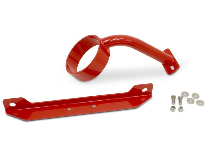
Shop Parts in this Guide
Installation Instructions:
These instructions follow the installation of the above referenced BMR drive shaft loops I purchased from American Muscle. I have a 2006 Roush supercharged Mustang GT, automatic with shorty ceramic coated headers, cats deleted, Pypes™ off-road “H” pipe and after market rear mufflers. I drag race my car mostly and I plan on keeping the stock two piece stock driveshaft for now. I decided it was time to add these loops for safety reasons at the track. Overall, the parts all came nicely packaged with all the necessary hardware for the install. BMR makes quality parts.
Installation Notes
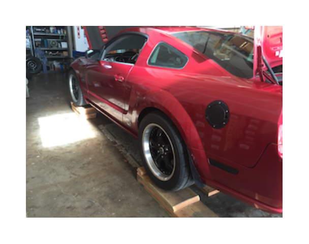
Me and a buddy, Patrick aka “Nasty GT”, did the install at his warehouse with jack stands and using custom wooden stands. Safety first when you’re you’re working on your back under your car! For this install, make sure you have good rear jack stands. Place them on the differential axle tubes. The goal here is to get the rear wheels off of the ground so you can rotate the driveshaft. The wood you see in this image is not touching the tires, We keep them there for safety reasons.
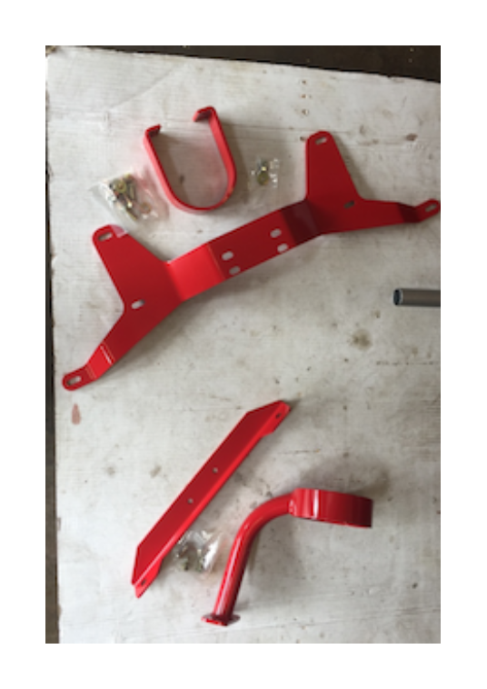
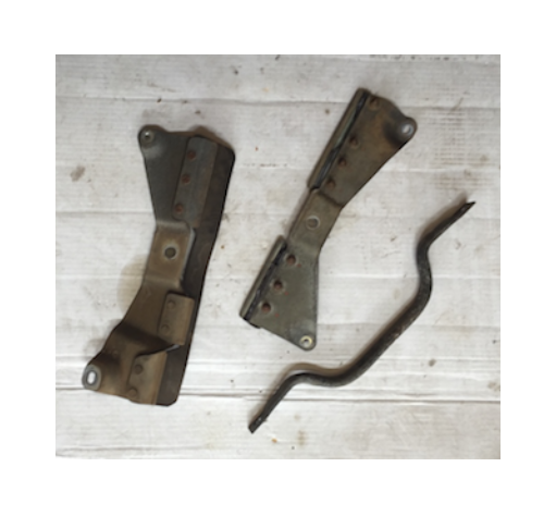
Here are the parts for the front and rear laid out on the floor. The bottom two pieces are for the front of the car, just behind the transmission. The top parts are for the rear section of the two-piece driveshaft. You can use these instructions for either set. The front loop is easier to install. The rear takes a little more time to get the larger “batwing” brace piece mounted.
First of all, let me state that I didn’t follow the instructions that came from BMR. I decided to remove the driveshaft and drop my exhaust. My exhaust has sections to it and it’s easier to just remove the exhaust clamps. Removing everything allows you to inspect the parts you remove and to understand how things go together. This also gives easy access to bolts and nuts. If you choose the methods used by BMR, these instructions will still help you.
1. I started out removing the front u-joint coupling on the driveshaft - the transmission side. Be sure and make a nice visible mark on the part and the flange on the transmission so you install the driveshaft in the same position. I used white paint. Do the same for the rear. There are four 12 point 12 mm bolts. Be sure and have the correct socket. During this procedure, you’ll have to go back and forth in the car, putting the car in Park with the parking brake engaged and neutral with no parking brake. This goes better with a buddy and allows you to rotate the driveshaft into position to get your ratchets in place. On re-install, you dab a small amount of blue thread locker on the threads of these bolts.
2. You’ll probably have to tap the connection with a rubber hammer and use a large
screwdriver to separate it from the transmission flange.
At this point, the driveshaft will only move back a few inches. It will not clear the flange
all of the way to lower it and slip the loop over it. There’s a pin that sticks out a few
inches which prevents you from dropping the driveshaft. BMR instructs you to support
the transmission and remove the transmission brace. Again, I’m not going to do this because I want to remove the driveshaft completely from the car.
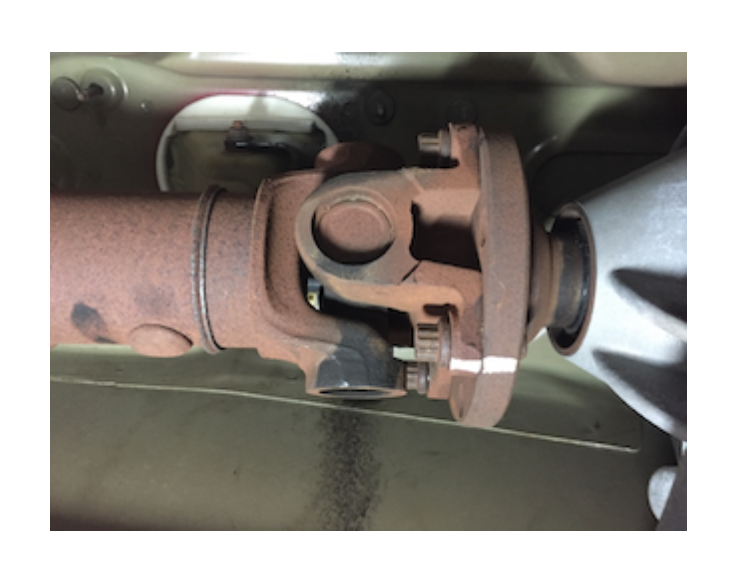
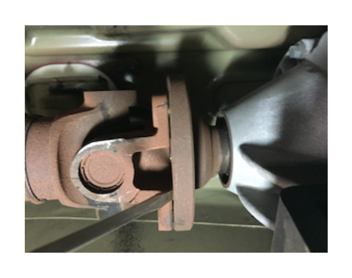
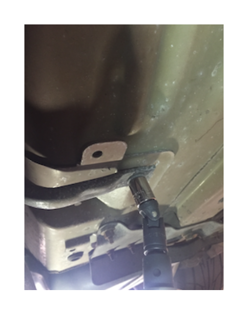
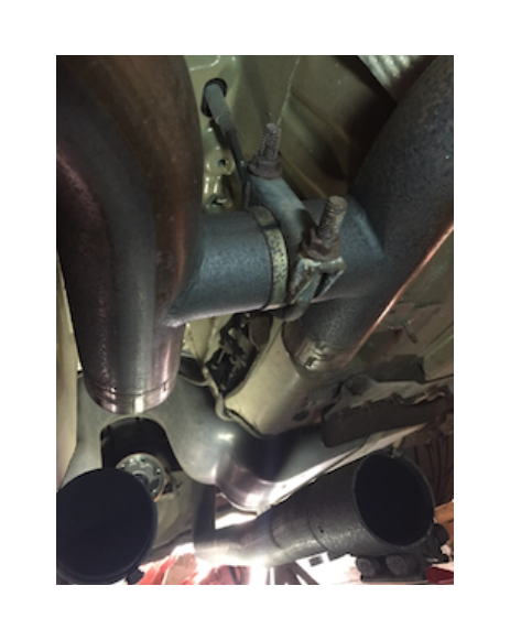
3. The center driveshaft brace/joint is removed next. It’s a 13mm bolt and you’ll need an extension and universal to get to the bolt. The next image shows one side of the brace with a bolt coming out. You can see my exhaust pipe in the bottom foreground. ! Please take notice that there is a thick spacer between this bracket and the mounting hole. Important this goes back when you re-install this part! See next image. !
Please take notice that there is a thick spacer between this bracket and the mounting
hole. Important this goes back when you re-install this part! See next image.
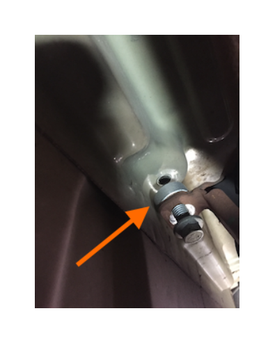
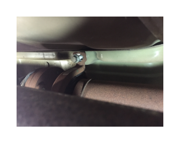
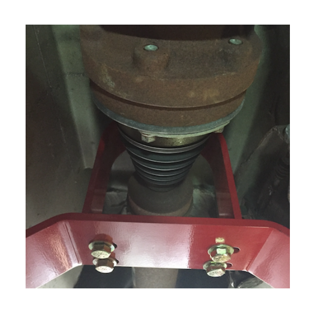
4. On my car, there was a round metal piece (some cars may not have this part) that went from one side of the tunnel to the other. It’s the part shown on the right below. Remove this along with the air flap brackets shown. Retain the bolts and nuts. You will use them to install the new rear tunnel brace. You do not re-install these parts.
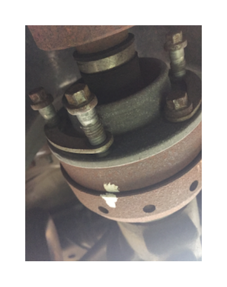
5. Moving to the rear. Remove the six, 6 point, 10mm bolts from rear driveshaft joint. Again, you’ll have to rotate the driveshaft to get to each bolt. Notice the white mark and the connected washers. There will be a noticeable outline of the washers left on the flange, so when you re-install the washers, you’ll know where they go.
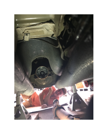
Once these bolts are removed, you can straddle the drive shaft, move it forward out of the rear differential cup flange, then feed it backwards with the help of a friend. Do not drop the driveshaft. It will slide out between the exhaust pipes towards the rear under the differential. This image is looking to the rear of the car.
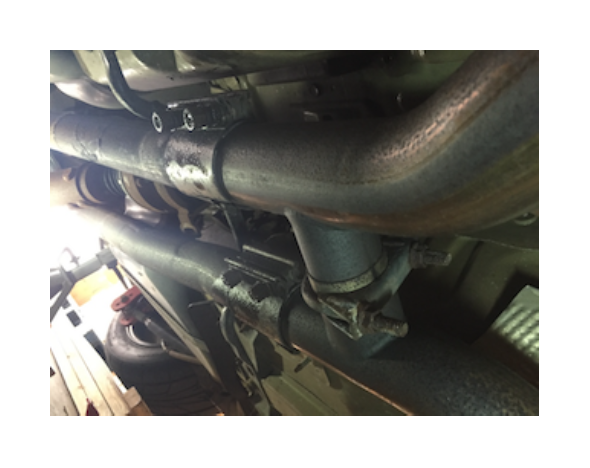
6. I dropped the pieces of my exhaust next. Soak with a thread/rust spray. We dropped the exhaust for more clearance and because the Pypes™ off-road H-pipe had the hanger attachment bolt in the way of the transmission support bracket bolt. No big deal, it all comes off quickly.
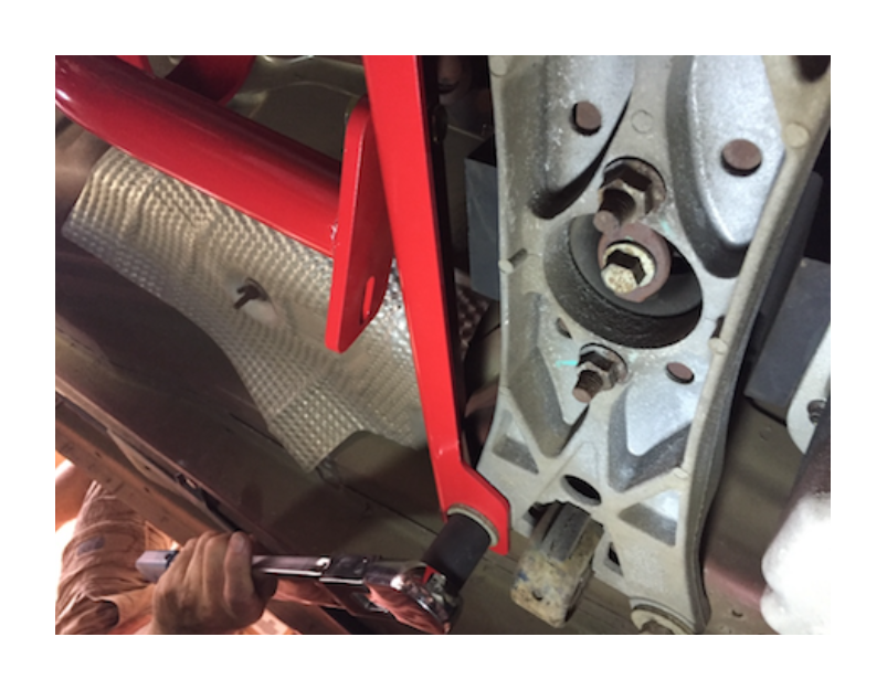
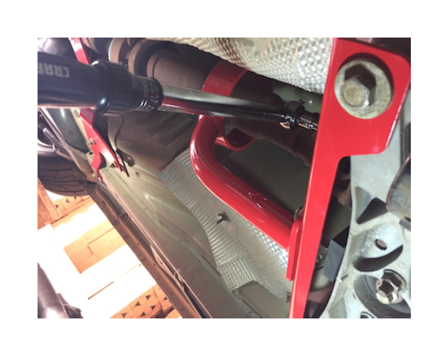
7. Moving to the front, remove the two 15mm rear transmission mounting brace bolts. This is where you attach the front loop brace. The loop itself will be slipped over the driveshaft and attached to this new BMR bracket using the two supplied bolts, washers and nuts. Re-torque these two transmission mount bolts to 55 ft-pounds.
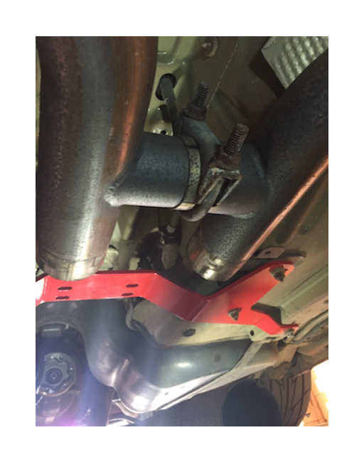
8. Moving to the rear, it’s time to mount the “batwing” bracket. The bend in it goes up towards the interior of the car. You’ll see where the part fits over the three attachment points on either side of the tunnel. Use the two nuts and the bolt you removed earlier and torque to 20 ft-pounds. This photo is looking toward the rear of the car.
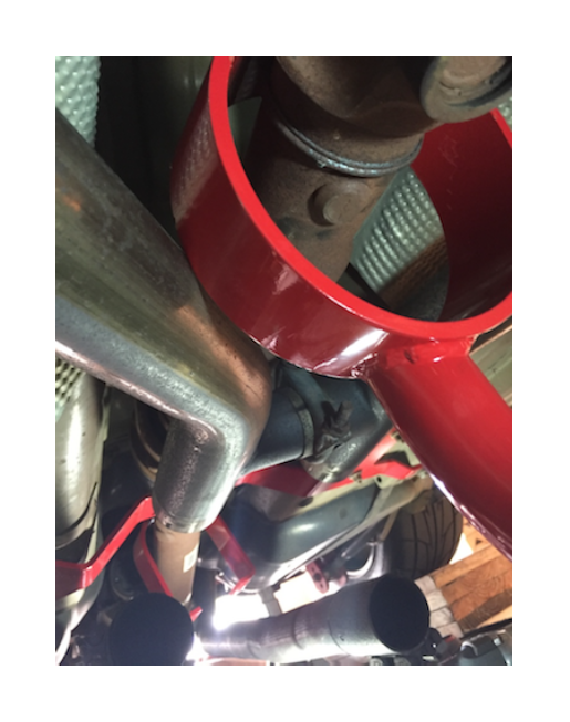
9. OK, time to slide the driveshaft back in! This next picture is looking towards the rear of the car too. You can see where we’ve slipped the rear and front loops over the drive shaft as the shaft is being placed back in place.
10. On the front drive shaft loop, loosely put the provided mounting bolts into the previously installed transmission side bracket. Install the front u-joint assembly on to the transmission flange and torque the 12 point bolts to 72 ft-pounds. Be sure to align your white marks and apply a small amount of Locktite to the bolt threads. Go ahead and center the loop over the shaft and tighten the two mounting bolts. No torque specs are given here, I did mine at 45 ft-pounds. The washers go over the head of the bolts. The nuts have locking nylon inserts on them. The bolt head is 15mm, the nut is 14 mm.
11. Moving to the rear, install the driveshaft into the differential mounting cup flange, align your white marks. Torque these 10 mm bolts to 50 ft-pounds. Apply Locktite to the threads. You’ll have to spin the driveshaft and lock it in place as you tighten the bolts. Using the four nuts and bolts provided, install the rear loop. Place the washers over the head of the bolts. Again no specs for these, but I tightened them to 45 ft-pounds. The loop is designed to fit near the center driveshaft coupling. If this joint fails, the driveshaft will not fall, catching the ground and possibly vaulting the car.
12. Button up your exhaust, check that your tail pipes are even and centered in the rear bumper openings if you removed your exhaust and you are done. Be sure to take a few minutes and go over your work. Check your work!
SUMMARY. Overall, it took us old guys most of the morning to get the car ready, remove and install parts and clean up. A fairly basic install. BMR makes quality parts and I love the red powder coating they use. Fitment was spot on. And now that I’m moving into the 11’s, I feel better knowing these loops are keeping me from pole vaulting in the event of a u-joint failure. I hope this write-up helps you.
