 FREE 1 to 3-Day Delivery on Orders $119+ Details
Best Sellers


How to install a Ford Racing High Performance Intake Manifold on your 2005-2010 Mustang
Shop Parts in this Guide
Installation
KIT CONTENTS:
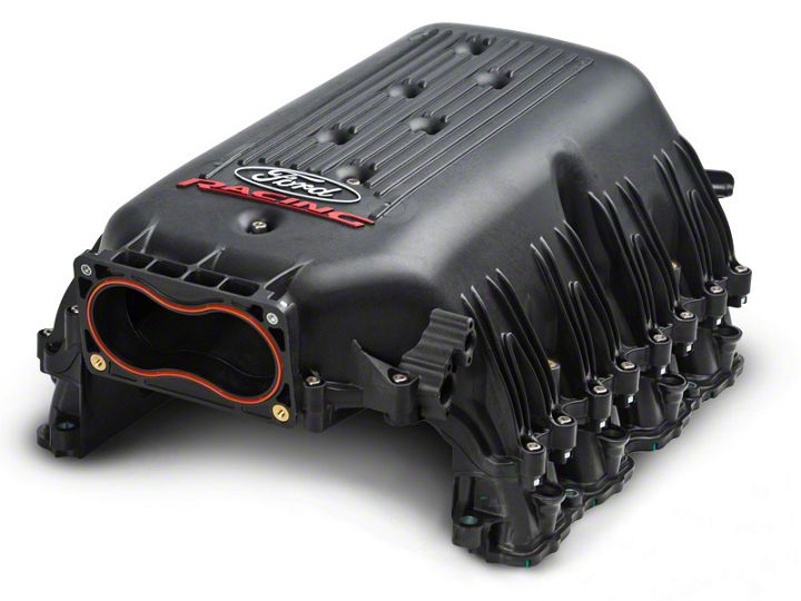
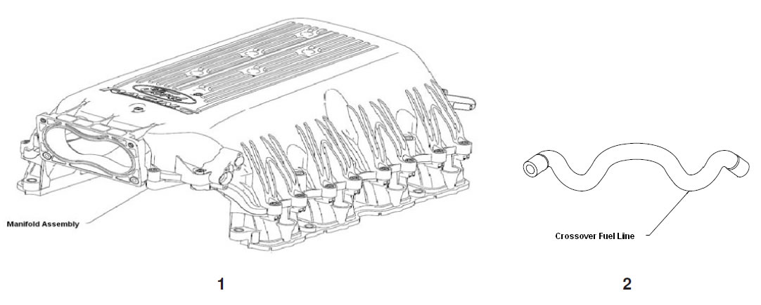
1. Intake Manifold Assembly
2. Crossover Fuel Line
3. Component Kit
4. Throttle Body Bolts and Washers (not shown in diagram below)
5. Assembly Instructions (this document)

NOTE: FORD RACING AND THE MANUFACTURER HAVE ONLY VALIDATED THIS INTAKE MANIFOLD IN ITS AS-MANUFACTURED STATE AND IN ITS SPECIFIED ASSEMBLY CONFIGURATION AS DEFINED ON THE FOLLOWING PAGES. PLEASE NOTE THAT THE USER ACCEPTS ALL RISKS IF THEY CHOSE TO MAKE ANY MODIFICATIONS TO THE INTAKE MANIFOLD; INCLUDING, BUT NOT LIMITED TO, MANIFOLD DISASSEMBLY. WHILE THIS INTAKE MANIFOLD HAS THE APPEARANCE OF A TAKE-APART INTAKE MANIFOLD, THIS IS NOT INTENDED OR RECOMMENDED. THE INTAKE MANIFOLD HAS BEEN LEAK CHECKED AT THE FACTORY PRIOR TO DELIVERY AND DISASSEMBLY OF THE UPPER INTAKE ANIFOLD FOR INTERNAL MODIFCIATION OR INSPECTION, WILL MAKE IT VERY DIFFICULT ND/OR IMPOSSIBLE FOR THE CUSTOMER TO RESEAL THE INTAKE MANIFOLD TO THE ORIGINAL SPECIFICATIONS.
FUEL SYSTEM PRESSURE RELEASE:
WARNING: Do not smoke, carry lighted tobacco or have an open flame of any type when working on or near any fuel-related component. Highly flammable mixtures are always present and may be ignited. Failure to follow these instructions may result in serious personal injury.
WARNING: Do not carry personal electronic devices such as cell phones, pagers or audio equipment of any type when working on or near any fuel-related component. Highly flammable mixtures are always present and may be ignited. Failure to follow these instructions may result in serious personal injury.
WARNING: Before working on or disconnecting any of the fuel tubes or fuel system components, relieve the fuel system pressure to prevent accidental spraying of fuel. Fuel in the fuel system remains under high pressure, even when the engine is not running. Failure to follow this instruction may result in serious personal injury.
NOTE: The Fuel Pump Driver Module (FPDM) is located in the spare tire stowage compartment. Disconnect the FPDM electrical connector(s).
STEP 1: Start the engine and allow it to idle until it stalls.
STEP 2: After the engine stalls, crank the engine for approximately 10 seconds to make sure the fuel injection supply manifold pressure has been released.
STEP 3: Turn the ignition switch to the OFF position.
INSTALLATION INSTRUCTIONS:
STEP 1: Disconnect battery at negative (black) terminal.
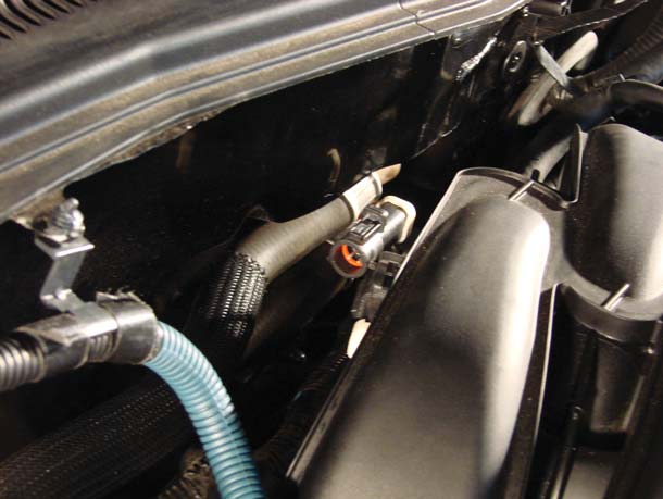
STEP 2: Disconnect electrical connections to throttle body, mass air flow sensor, fuel pressure sensor, fuel injectors and CMCV. Some connectors have a red lock on them. You will need to slide the lock back before you can disconnect the connector. The CMCV connector has a push-in retainer that needs to be removed from the bracket with a panel-popper tool. This connection does not get used with the new intake manifold.

STEP 3: Remove air intake tube or airbox. This requires a 5/16" socket for the clamp at the throttle body. Disconnect the vacuum line (VAC-A) from the inlet tube by rotating the green tab. NOTE: The end of the tab is in a groove so you will need to get the tab out of the groove before it will rotate. If equipped, you will need a 10mm socket to remove your Ford Racing cold air kit. Otherwise, you can just remove the lid from your stock airbox.
STEP 4: Disconnect vacuum tubes at front of intake manifold. It is easiest to use a flat screwdriver to depress the lip retainer on the top hose (VAC-C). The lower hose (VAC-B) with green clip just requires you to rotate the tab clockwise to loosen the clip and pull it off. Disconnect vacuum line at FPS (VAC-D) and rear of intake manifold (VAC-E).
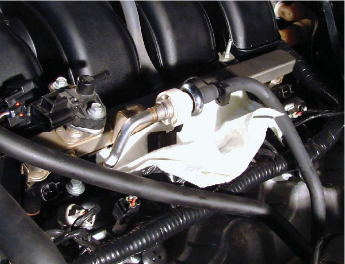
STEP 5: Fuel Pressure must be released before performing the following step! Disconnect the fuel line by first removing the safety clip. Put on safety glasses. Use a 5/8" fuel line disconnect tool to disconnect the fuel line.
WARNING: Fuel will spill out when you disconnect the line so it is best to place a rag below the connection to absorb the fuel that spills.
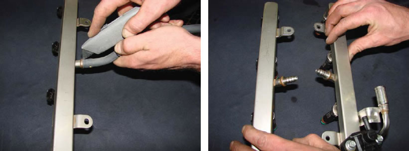
STEP 6: Unbolt fuel rails using an 8mm deep socket. Remove injectors from intake by gently wiggling them while applying pressure straight upward until they release from the injector bosses. Set aside for later modification.
STEP 7: Remove throttle body from intake using an 8mm socket for the top two bolts and a 10mm socket for the lower two bolts.
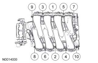
STEP 8: Unbolt intake manifold using a 10mm deep socket. The intake manifold should be unbolted in the reverse torque sequence pattern (see illustration on top of page 7 in this document). Remove the intake manifold and set aside.
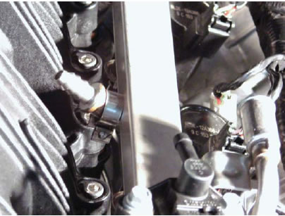
STEP 9: Remove the alternator bracket using 8mm and 10mm sockets. The lower hole on the push-in connector needs to be enlarged for the relocation of the connector. Enlarge the smaller of the two holes using a 1/4" diameter drill bit.
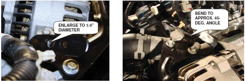
STEP 10: Reinstall alternator bracket and torque bolts to 89 in-lb. Using pliers or an adjustable wrench, bend the tab forward to approximately a 45-degree angle as shown in the figure above. You may need to adjust this angle until there is enough clearance for the alternator wire to clear the intake manifold.
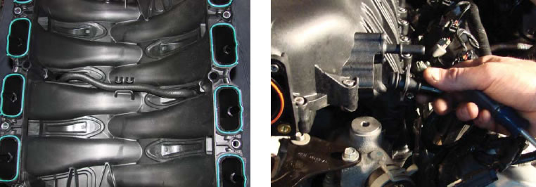
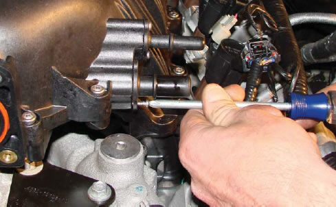
STEP 11: On new intake manifold, install supplied crossover fuel line to the underside of the intake manifold with the paint mark oriented toward the driver’s side of the vehicle. Using a #2 Phillips screwdriver, remove the larger diameter vacuum nipple. This is required to gain access to the front intake bolt. Leave it off until intake bolts are torqued.
STEP 12: Install intake manifold using supplied bolts. The two long bolts (M6x110) and thin washers are the two center bolts. These should be started first. Do not tighten them yet. The mid-length bolts (M6x50) are the front two bolts and the short bolts (M6x35) are for the remaining locations. Hand-start all bolts before snugging or torquing any bolts. Torque intake bolts to 89 in-lb starting with the two center bolts alternating fore and aft while working your way to the ends of the intake (see illustration below).
STEP 13: To modify the fuel rail assembly, cut the fuel line off of the nipple as shown in the figure below. Discard old fuel line.
STEP 14: NOTE: Replace any damages O-rings. Lubricate the O-rings on the fuel injectors with clean engine oil to ease installation.
With all injectors aligned with bosses in intake, push gently downward on rail until all injectors are seated in the bosses. Duplicate for opposite side. Do not install rail retaining bolts. You may need some play to install the new fuel line. It is also convenient to slip the fuel line clamps over the nipples prior to connecting the fuel crossover line.
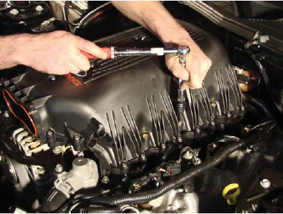
STEP 15: Connect supplied fuel line to nipples on fuel rails using the supplied clamps with a 9/32” socket driver. Do not over-tighten. Orienting the screw towards the back of the vehicle will provide for best aesthetics.
STEP 16: Install fuel rail bolts and torque to 89 in-lb.
STEP 17: Install throttle body using supplied M6x25mm bolts. Torque to 70 in-lb.
STEP 18: Reinstall the vacuum nipple at front of intake.
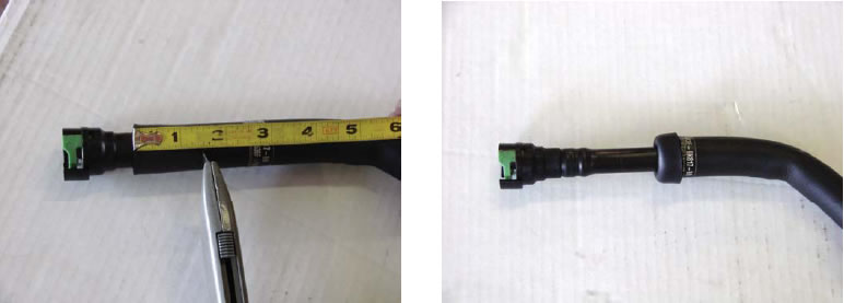
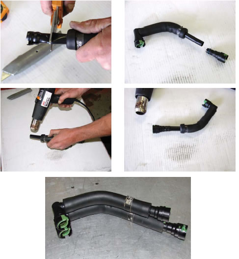
STEP 19: It is necessary to shorten the vacuum tube from the intake to the valve cover. This hose needs to be shortened by 1.5”. Start by cutting away 1.5” of the insulating cover. BE CAREFUL NOT TO CUT THROUGH THE PLASTIC INNER HOSE. Roll the insulating cover back over itself to expose more of the plastic hose. Cut 1.5" from the plastic hose. Measure from the end of the plastic hose, and not the connector. Next, remove the 1.5” section from the fitting. The next step is probably the most difficult task of this job, so be careful. With a heat gun on low, or a hair dryer on high, heat the end of the hose so that it is soft enough to slip over the barb on the hose end fitting. BE CAREFUL NOT TO OVER HEAT THE HOSE! Be sure the hose is fully seated on the fitting. The hose will shrink to a tight fit when it cools.
STEP 20: Connect vacuum line at rear (driver’s side) of intake manifold and fuel pressure sensor.
STEP 21: Connect MAF sensor, TPS sensor, TCS sensor and all fuel injector connectors.
STEP 22: Reconnect negative terminal on battery.
PRESSURIZE FUEL SYSTEM:
STEP 1: When the fuel system service/modifications are complete, connect the FPDM electrical connector(s).
NOTE: It may take more than one key cycle to pressurize the fuel system.
STEP 2: Cycle the ignition key and wait 3 seconds to pressurize the fuel system. Check for leaks before starting the engine.
STEP 3: Start the vehicle and check the fuel system for leaks.
WARNING: DO NOT DRIVE VEHICLE UNTIL CALIBRATION UPDATE IS COMPLETE! ENGINE DAMAGE MAY OCCUR!
