 FREE 1 to 3-Day Delivery on Orders $119+ Details
Best Sellers


How to Install a Ford Racing GT500 Brake Cooling Shields on your 2005-2013 Mustang
Shop Parts in this Guide
Please visit www.fordracingparts.com for the most current instruction information
! ! ! PLEASE READ ALL OF THE FOLLOWING INSTRUCTIONS CAREFULLY PRIOR TO INSTALLATION. AT ANY TIME YOU DO NOT UNDERSTAND THE INSTRUCTIONS, PLEASE CALL THE FORD RACING TECHLINE AT 1-800-367-3788 ! ! !
Kit Includes:
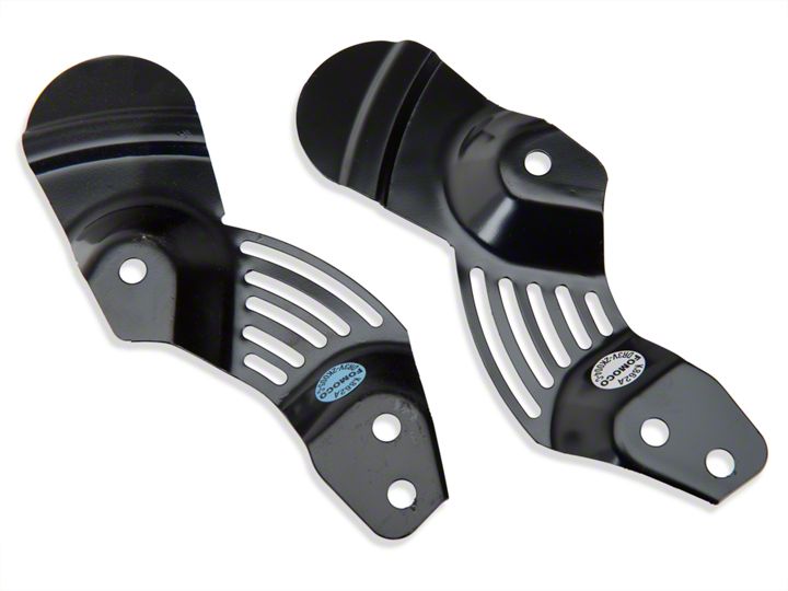
1 RH brake cooling shield
1 LH brake cooling shield
4 brake shield bolts
4 caliper mounting bolts
REMOVAL:
STEP 1: Remove the wheel and tire.
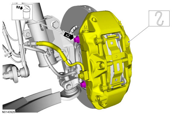
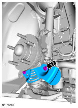
STEP 2: Remove caliper by removing the 2 caliper mounting bolts. Discard bolts.
NOTICE: Do not allow the brake caliper, brake pads and anchor plate assembly to hang from the brake hose or damage to the hose may occur.
Discard the specified component. Follow local disposal regulations. Relocate and support the component.
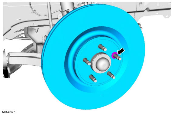
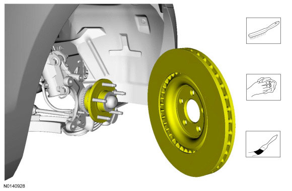
STEP 3: Remove brake rotor
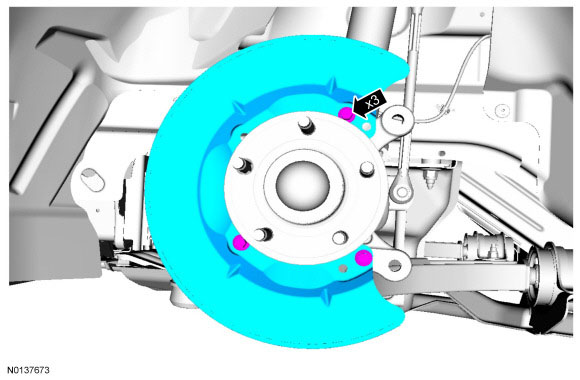
STEP 4: Remove the 3 bolts and remove dust shield and discard.
INSTALLATION:
STEP 1: Use 2 new bolts and install new High Performance Brake Cooling Shields.
• To install, tighten to 20 Nm (177 lb-in).
STEP 2: Install brake rotor
NOTICE: Do not use an abrasive sanding disc since it will remove paint or other protective finishes from the wheel or metal from the mounting surfaces, adversely affecting corrosion protection and brake disc lateral runout.
Wire brush rotor to hub mating surfaces. Clean Metal Brake Parts Cleaner. Apply High Temperature Nickel Anti-Seize Lubricant with a brush.
STEP 3: Install brake caliper
STEP 4: Tighten the new brake caliper bolts to 115 Nm (85 lb-ft).

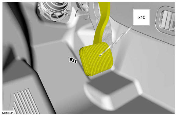
STEP 5: After both calipers are installed, pump brake pedal 10 times.
INSTALL WHEELS:
STEP 1: WARNING: When a wheel is installed, always remove any corrosion, dirt or foreign material present on the mounting surface of the wheel and the mounting surface of the wheel hub, brake drum or brake disc. Make sure that any fasteners that attach the rotor to the hub are secured so they do not interfere with the mounting surfaces of the wheel. Failure to follow these instructions when installing wheels may result in the wheel nuts loosening and the wheel coming off while the vehicle is in motion, which could result in loss of control, leading to serious injury or death to vehicle occupant(s).
NOTICE: Make sure to apply a thin coat of anti-seize lubrication only to the interface between the wheel pilot bore and the hub pilot. Do not allow the anti-seize to make contact with the wheel-tobrake disc/drum mounting surface, wheel studs, wheel nuts, brake pads or brake disc friction surfaces or damage to components may occur.
Clean the wheel mounting surfaces and apply a thin coat of anti-seize to the wheel hub pilot surface (wheel only).
STEP 2: Install the wheel and tire assembly.
STEP 3: WARNING: Retighten wheel nuts within 160 km (100 mi) after a wheel is reinstalled. Wheels can loosen after initial tightening. Failure to follow this instruction may result in serious injury to vehicle occupant(s).
NOTICE: Failure to tighten the wheel nuts in a star/cross pattern can result in high brake disc runout, which will speed up the development of brake roughness, shudder and vibration.
NOTE: The wheel nut torque specification is for clean, dry wheel stud and wheel nut threads.
Install the 5 wheel nuts by hand.
• Tighten the wheel nuts in a star/cross pattern to 135 Nm (100 lb-ft).
