 FREE 1 to 3-Day Delivery on Orders $119+ Details
Best Sellers


How to Install a Ford Racing Short Throw Shifter - TR-6060 on Your 2007-2009 Mustang GT500
Installation
OVERVIEW:This kit is designed for use on the 2007-2008 SVT Mustang. The use of a floor hoist is recommended. If you do not have access to one, use a hydraulic floor jack and jack stands to raise the vehicle.
! ! ! CAUTION: JACK STANDS MUST BE USED ON A LEVEL SURFACE AND BE SECURELY SEATED.FAILURE TO DO SO MAY RESULT IN PERSONAL INJURY OR VEHICLE DAMAGE ! ! !
REMOVAL INSTRUCTIONS:

Pic. 1
Pic. 2
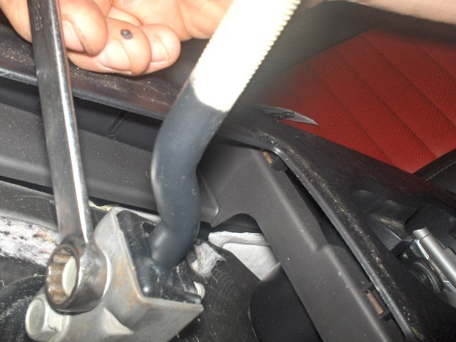
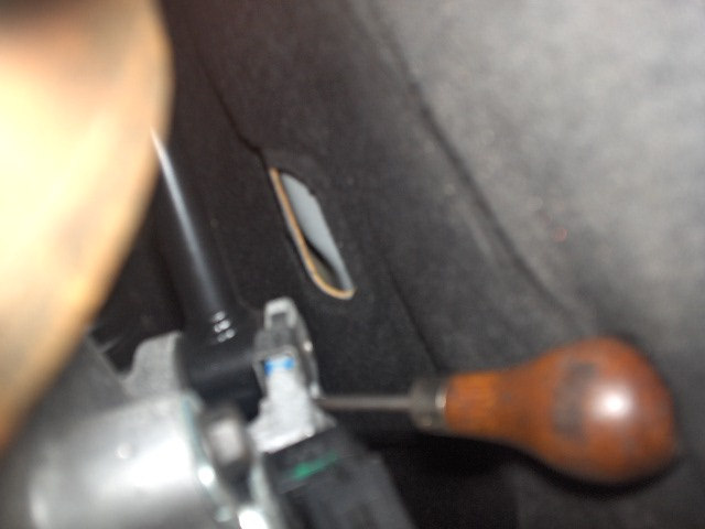
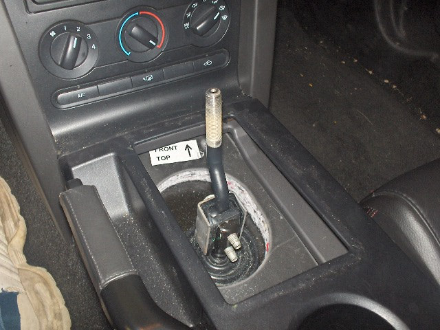
STEP 1:Remove the gearshift lever knob and boot. Rotate counter clockwise (see Pic. 1).
STEP 2:Remove the upper gearshift lever bolts and the upper gearshift lever (see Pic. 2).
Pic. 3
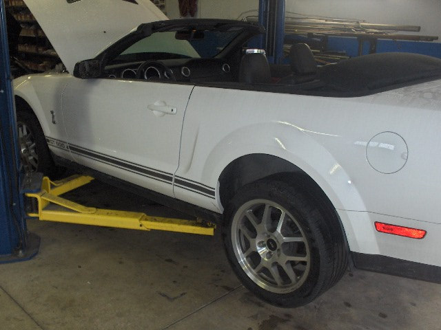
STEP 3: With the vehicle in NEUTRAL, position it on a vehicle hoist or secure on jack stands (see Pic. 3).
Pic. 4
Pic. 5
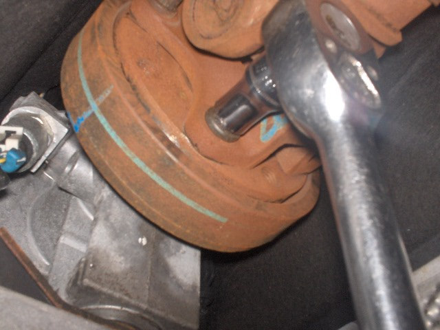
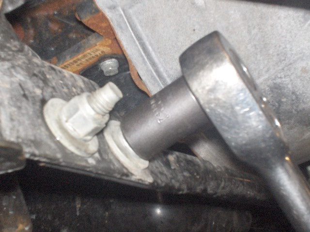
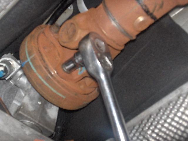
STEP 4:Mark driveshaft-to-transmission flange orientation for reassembly. Then, remove the driveshaft four(4) flange bolts (see Pic. 4).
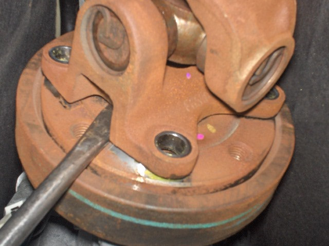
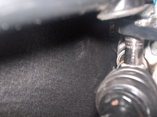
STEP 5:Using a suitable pry tool as shown (see Pic. 5), disconnect the driveshaft flange from transmission and secure with mechanics wire.
Pic. 6
Pic. 7
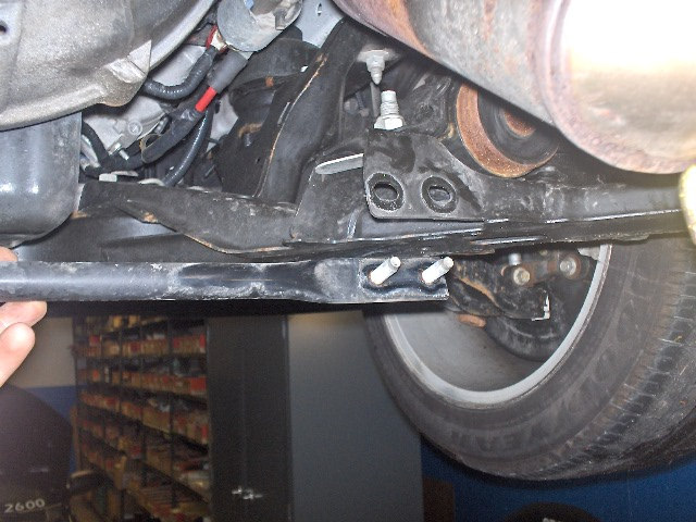
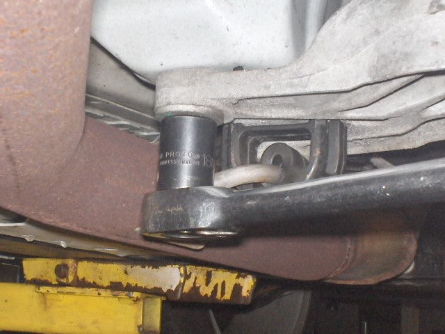
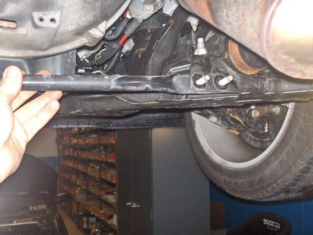
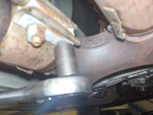
STEP 6:Remove the four (4) sub frame cross brace bolts (see Pic. 6) and the sub frame cross brace(see Pic 7).
Pic. 8
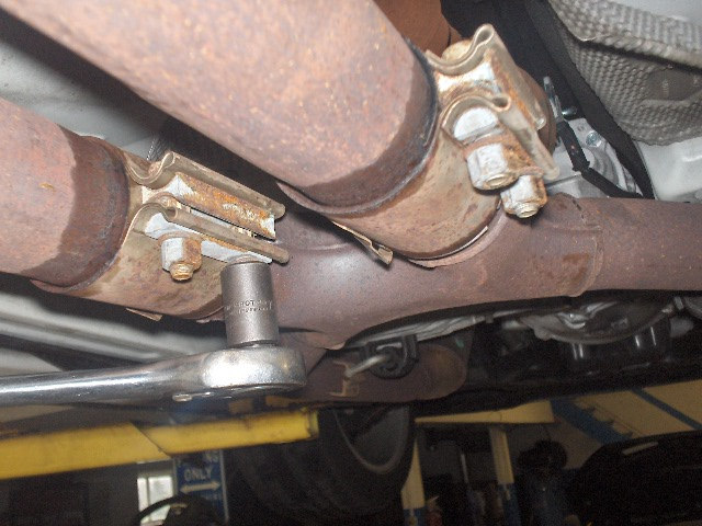
STEP 7:Remove the four (4) exhaust bolts and separate exhaust (see Pic. 8).
Pic. 9
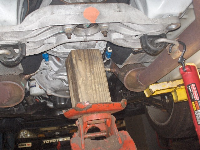
STEP 8:Using a suitable transmission jack, support the transmission (see Pic. 9).

Pic. 10
Pic. 11
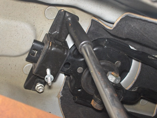
STEP 9:Remove the four (4) rear transmission mount outer bolts (see Pic. 10).
STEP 10:Lower the transmission to access shifter and remove the two (2) gearshift lever nuts (see Pic. 11).
Pic. 12
Pic. 13
Pic. 14
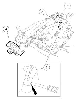
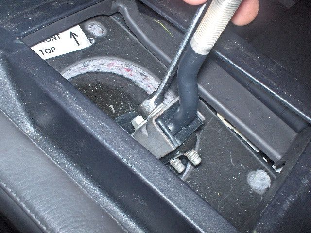
STEP 11:To remove the gearshift lever assembly:
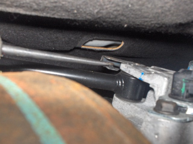
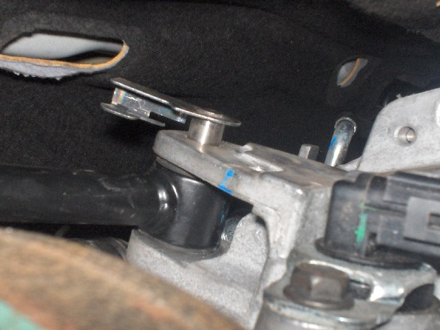
1. Insert a pick into the lower hole to unlock the clip (see Pic. 12 and line drawing Item 1).
2. Rotate the gearshift lever retainers, then remove the retainers (see Pics. 13, 14 and line drawing Item 2).
Pic. 15

Pic. 16
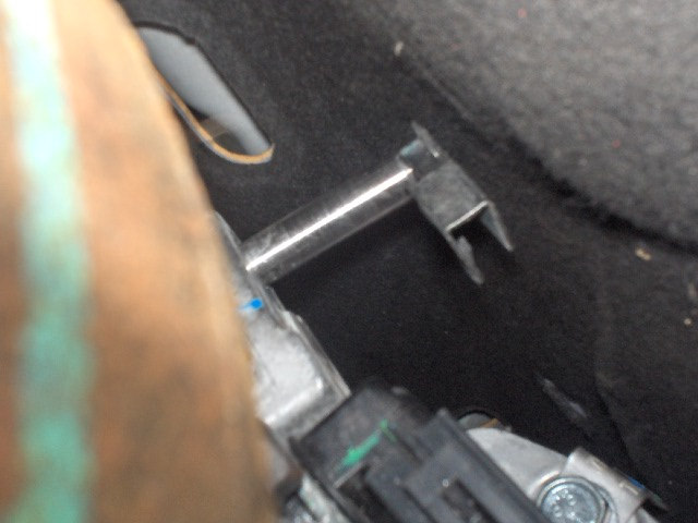
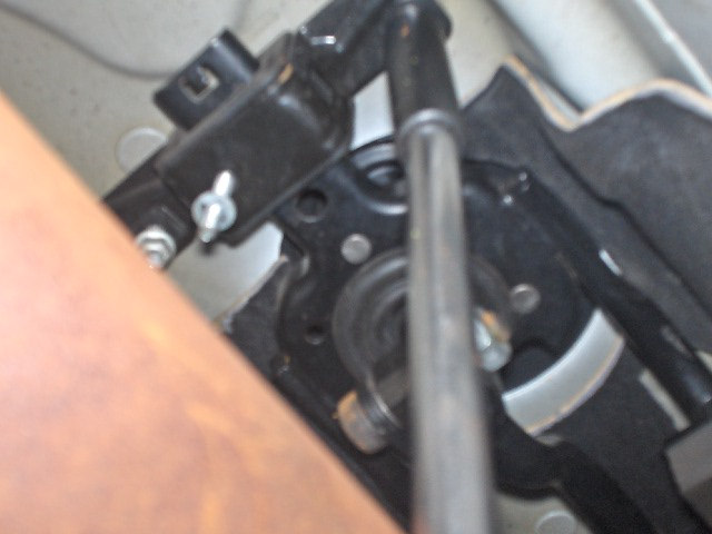
1. Remove the lower gearshift lever bolt (see Pic. 15 and line drawing Item 3).
2. Remove the gearshift lever assembly from the vehicle (see Pic. 16).
SHIFTER REMOVAL LINE DRAWING

Pic. 17
Pic. 18
STEP 1:Install new gear shifter in vehicle:
1. Reinstall lower gearshift lever bolt (see Pic. 17). Tighten to 40 Nm (30 lb.-ft.).
2. Make sure to snap the gearshift lever retainers into the locked position (see Pic. 18).
3. Carefully position the gearshift lever into the lower shift boot. Make sure the lever is through the boot.
Pic. 19
Pic. 20
STEP 2:Install the two (2) rear gearshift nuts and secure (see Pic. 19).
STEP 3:Install driveshaft-to-transmission flange with four (4) bolts (use thread lock on bolts). Make sure to realign orientation mark and tighten to 103 Nm (76 lb.-ft.) (see Pic. 20).
Pic. 21
Pic. 22
Pic. 23
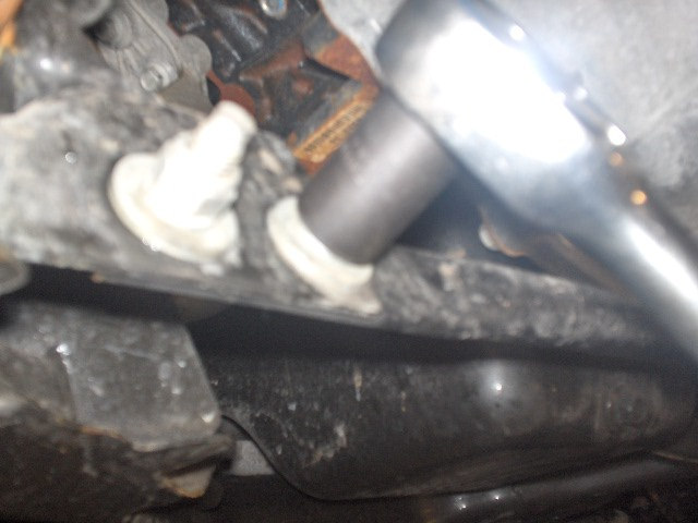
STEP 4:Raise transmission into correct location and reinstall the four (4) transmission mount outer bolts(see Pic. 21). Torque bolts to 63 Nm (46 lb.-ft.).
STEP 5:Install the four (4) sub frame cross brace bolts and the sub frame cross brace (see Pic. 22). Torque to 48 Nm (35 lb.-ft.) (see Pic. 23).
Pic. 24
Pic. 25
STEP 6:Join exhaust and install four (4) exhaust clamp bolts and tighten (see Pic. 24).
STEP 7:Install the upper gearshift lever bolts and the production upper gearshift lever (see Pic. 25). Torque bolts to 35 Nm (26 lb.-ft.).
Pic. 26
Pic. 27
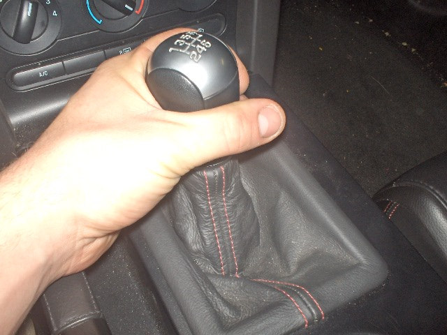
STEP 8:Install the production gearshift lever knob and boot (see Pics. 26 and 27).
TORQUE SPECIFICATIONS:
Upper gearshift lever bolts 35 Nm (26 lb.-ft.)
Driveshaft flange bolts 103 Nm (76 lb.-ft.)
Transmission outer mount bolts 63 Nm (46 lb.-ft.)
Lower gearshift lever bolt 40 Nm (30 lb.-ft.)
Sub frame cross brace bolts 48 Nm (35 lb.-ft.)
Best Sellers
Related Guides
-
Installation
-
Installation
-
Installation
