 FREE 1 to 3-Day Delivery on Orders $119+ Details
Best Sellers


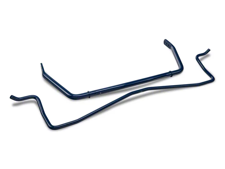
How to Install Ford Racing Sway Bar Kit on your 2005-2013 Mustang GT Coupe
Installation Time
2 hours
Tools Required
- Lug Wrench
- 4mm Hex or Allen Key
- 7mm Socket
- 8mm Socket
- 14mm Deep Socket
- 15mm Socket
- 15mm Deep Socket
- 15mm Open End Wrench
- 17mm Open End Wrench
- 18mm Ratcheting Box End or Deep Socket
- 19mm Wrench or Socket (2)
Shop Parts in this Guide
Tools Required:
• Lug Wrench
• 4mm Hex or Allen Key
• 7mm Socket
• 8mm Socket
• 14mm Deep Socket
• 15mm Socket
• 15mm Deep Socket
• 15mm Open End Wrench
• 17mm Open End Wrench
• 18mm Ratcheting Box End or Deep Socket
• 19mm Wrench or Socket (2)
This is intended as a supplement to the instructions which came with the kit. Since torque specs were not provided with the instructions, during removal I noted the “tightness” of the item I was removing and tried to replicate that when I did the install. I suggest you do the same.
1. Safely support car and remove all 4 wheels (you could probably do this project with the wheels still on the car, but it will make access much easier if you remove them)
2. Remove the 3 bolts holding the plastic shield which covers the oil filter (8mm hex). See green arrows in Figure 1.
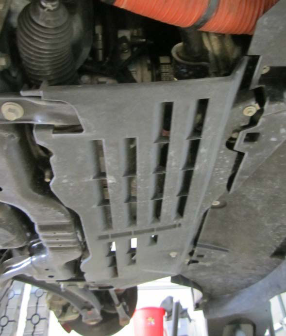
Figure 1
3. Remove the front drop links from the ends of the stock sway bar using a 17mm open end wrench and an 18mm deep socket or box end. See Figure 2.
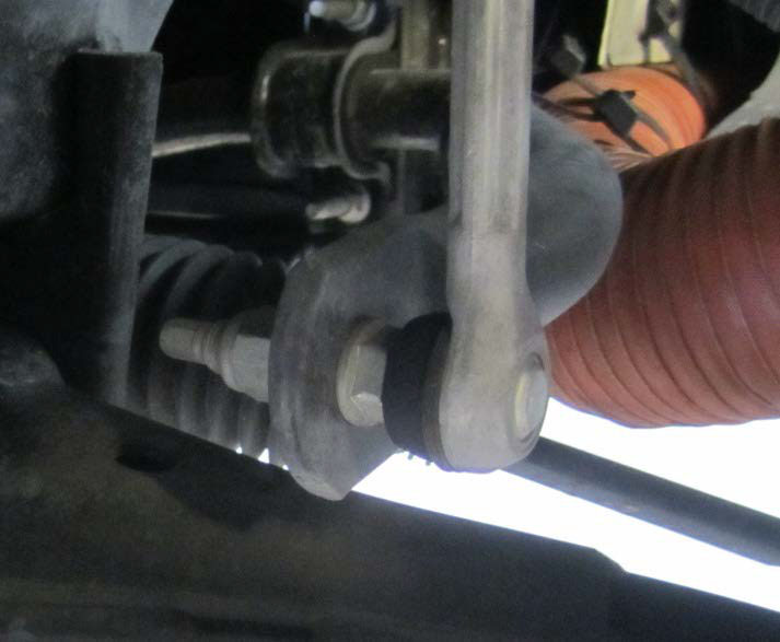
Figure 2
4. Remove the bushing brackets from the frame mount points (15mm deep socket). See Figure 3. The bolts are held in place by spring clips and will be reused for the installation of the new bar.
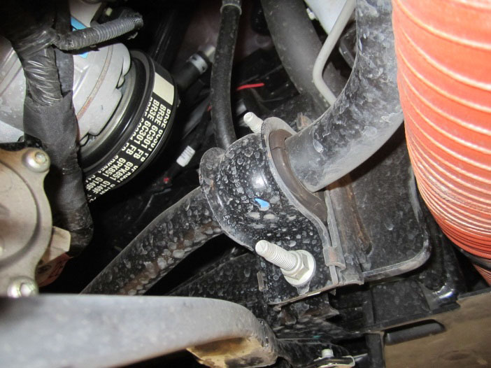
Figure 3
5. According to the provided instructions, removal of the front bar should be possible at this time. It was my experience that this was not possible without removal of the cross member support (which the plastic shield removed in step 2 hangs from). If you find this necessary as well, remove:
a. The 7mm hex head screws holding the plastic shield/splitter which attaches to the chin spoiler (identified in Figure 4)
b. The 6 bolts and 2 nuts (all 15mm) shown with blue arrows in Figure 4.
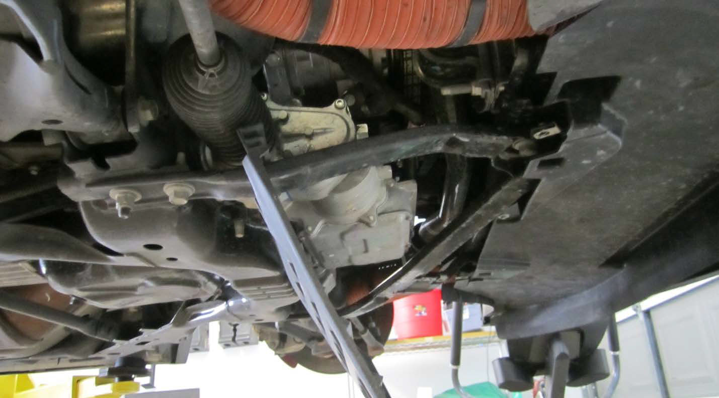
Figure 4
6. Remove the existing sway bar. Note direction of bends/shape for ease of installation of new bar (stock bar has sticker indicating orientation, Ford Racing bars do not). E.g. center section bends down.
7. Lubricate inside of new bushing with supplied lubricant. Bushings also have grease fittings for maintenance lubrication.
8. With bushing cut facing down insert it over the new bar OUTSIDE of the locating collars. Repeat for other side.
9. Slide U shaped mounting brackets over the bushings.
10. Fasten U shaped mounting brackets to frame mount points (bolts held by spring clips). Requires 15mm deep socket.
NOTE: Because of the elongated mounting holes on the Ford Racing brackets the bolts can become spaced too closely together. This causes the bolt heads (held by the spring clips) to slide down into the wider opening so they do not hold (or do not hold as well). Make sure to keep them spaced far enough apart that the bolt head makes full contact with the narrow section of the frame mount point. Bolts should stay pointed straight out (if they are at an angle then they are not properly seated in the narrow part of the frame slots). See Figure 5.
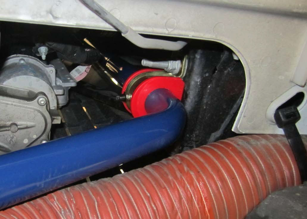
Figure 5
11. Attach drop links to the appropriate mounting hole in the sway bar end (see instructions provided with bar for adjustments and their impact) using 17mm open end and 18mm deep socket or ratcheting box end. Figure 6 show bar adjustment in middle position.
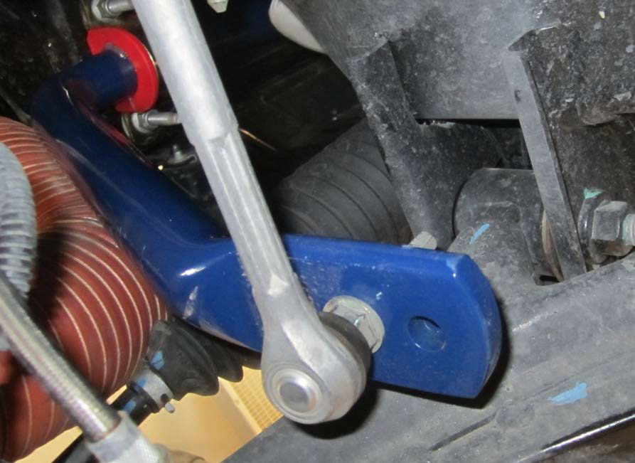
Figure 6
12. Tighten/check all front bar mounting and connection points.
According to instructions which accompanied the sway bar set, the V6 models do not have a factory rear sway bar and thus can proceed to Step 16.
13. Remove the two U shaped clamps which hold the rear sway bar ends to the shock mounts using 15mm deep socket or wrench. See Figure 7.
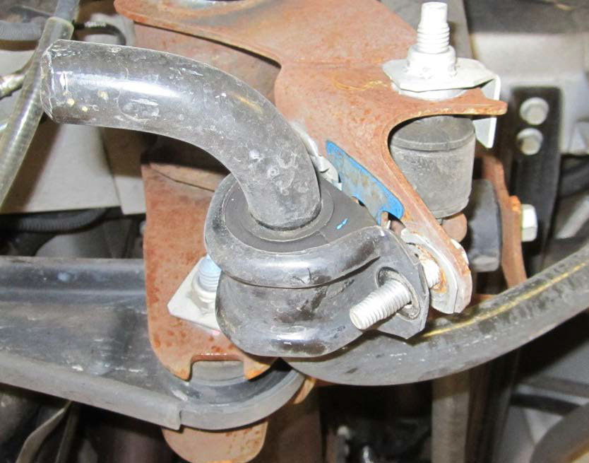
Figure 7
14. Remove the mounting bolts and retaining spring clips (they will not be used for new bar installation). See Figure 8.
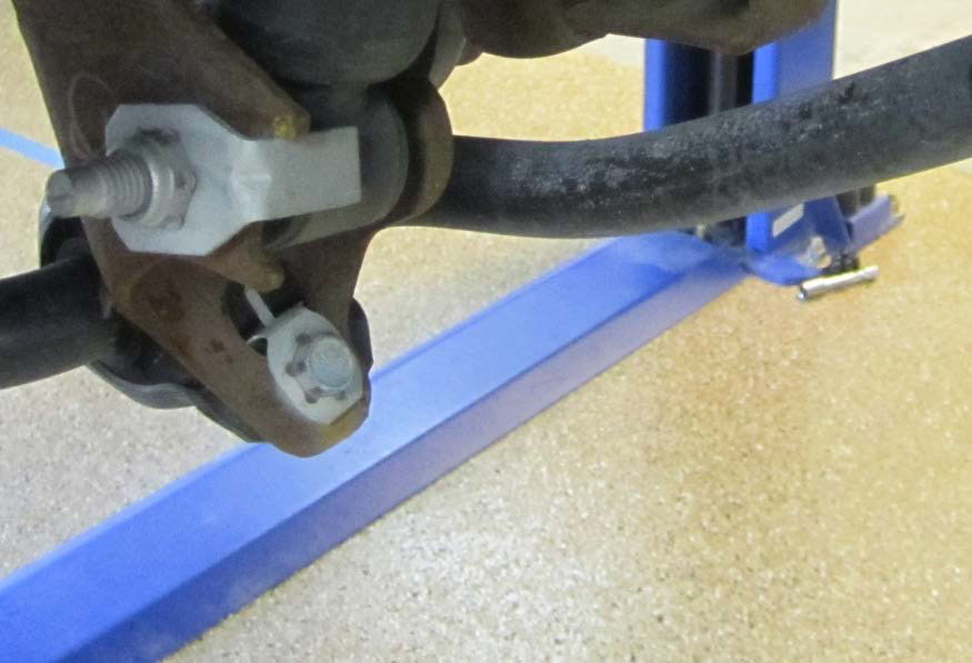
Figure 8
15. Remove the top bolts from the right and left rear end links using a 15mm wrench or socket. The existing bolts can be removed as they will not be reused. See bolts identified with orange arrow in Figure 9. NOTE: Bar will be free once these bolts are removed.
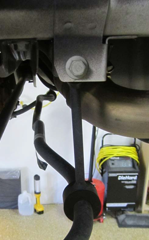
Figure 9
16. If the top bushings and sleeves are not already assembled, lubricate the inside of the bushing and insert bushing and sleeve into top of the link.
17. Lubricate the inside of the lower rear bushing and install it onto the new bar.
18. Attach the end links to the bar making sure that the opening of the end link faces the rear of the car. The hex cap screws use a 4mm hex/Allen key. I used a little Loctite on each of the hex cap screws. See Figure 10.
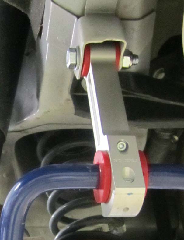
Figure 10
19. Using the supplied nut, bolt and washers, attach the tops of the end links to the factory mount points. For this you will need 2 x 19mm wrench/socket. Do not tighten. See Figure 10.
20. Lubricate the inside of the end bushings and install onto bar with the cut towards the ground.
21. Loosely assemble the bushing clamps bolts on both sides (2 per side) as follows: bolt through washer then U clamp, through lower shock mount point, backing plate, washer and then lock nut. Do not tighten. See Figure 11.
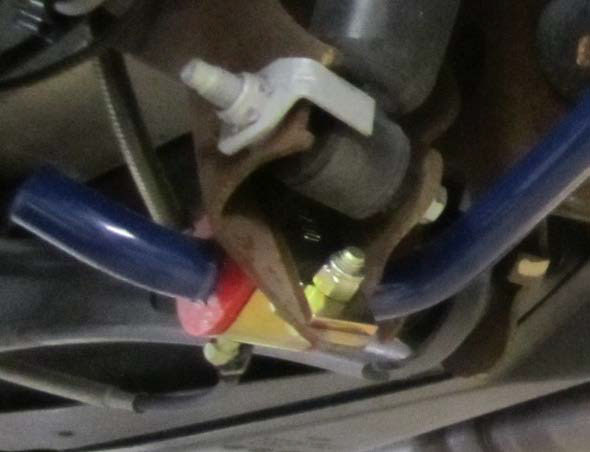
Figure 11
Note: Kit only had one washer per bolt. I inserted it under bolt head and did not use one under nut.
22. Reinstall wheels and tires onto car.
23. Lower the car so it is fully supporting itself on its own suspension. Race ramp style supports can be used under rear wheels to make access easier.
24. With car under its own weight, tighten all the rear mount points fully. For even great accuracy, the normal driver can be seated in the driver’s seat while performing this final tightening.
Installation Instructions provided by AmericanMuscle customer Ashley Griggs 10.09.12
