 FREE 1 to 3-Day Delivery on Orders $119+ Details
Best Sellers


How to Install Injen Power-Flow Cold Air Intake - Wrinkle Black on your Mustang
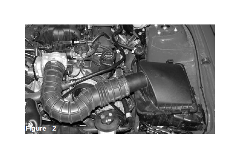
Stock air intake duct and air intake box
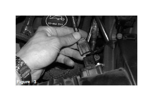
Mass air flow sensor harness clip is disconnected.
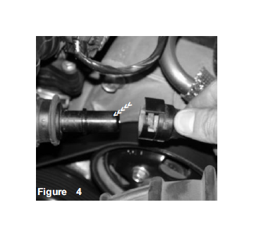
Crank case hard pipe breather line is disconnected.
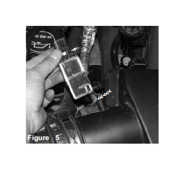
Two screws are unscrewed and the mass air flow sensor is removed from the sensor housing.
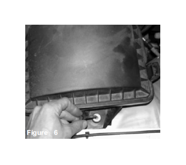
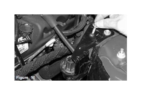
The screw is removed from the air box brace as shown above. This will allow the air box to be pulled out of the engine compartment.
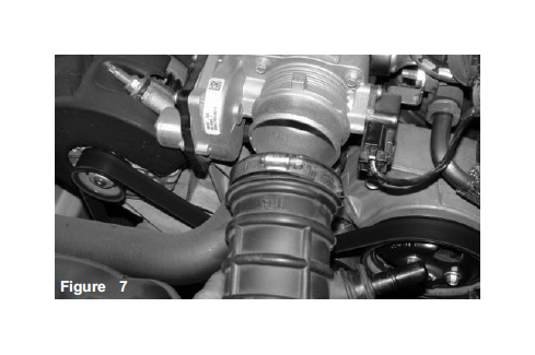
Loosen the clamp located on the air intake duct. Once the clamp has been loosened continue to remove the air duct from the throttle body.
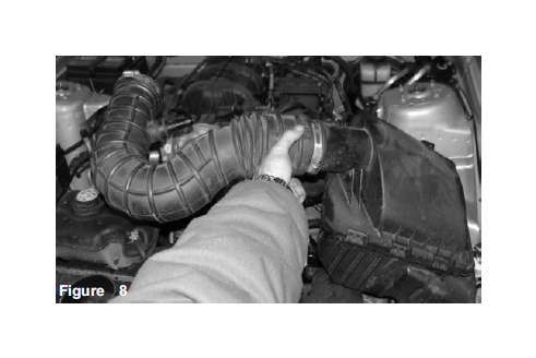
At this point, you should be able to remove the entire air intake duct and air intake box from the engine compartment.
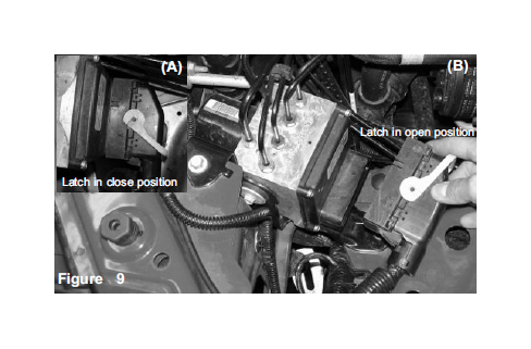
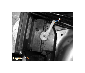
Locate the ABS solenoid latch (A). Flip the latch over to the right and pull the harness clip out of the ECU plug (B).
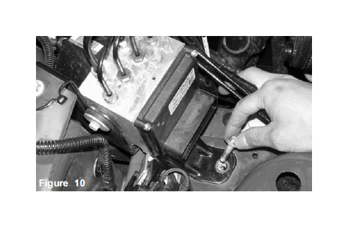
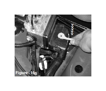
Remove the screw located at the base of the ABS solenoid brace.
Remove one of the screws from the shock tower mount bracket. This is the location where the new heat shield bracket will be attached.
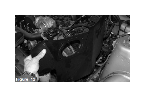
The heat shield is now lowered into the engine compartment and brackets are aligned.
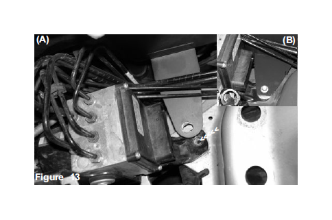
The lower heat shield bracket is lined up to the ABS solenoid brace (A). The stock screw is used to secure both the solenoid brace and the heat shield bracket (B), The screw is tightened at this point.
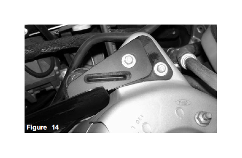
The top heat shield bracket is lined up to the shock tower mount side. The stock screw is used to hold the heat shield in place. Do not tighten the screw until the filter has been installed later in the instructions.
The solenoid harness is pressed into the ABS solenoid plug. The latch is now ready to pull into the close position.
The harness is connected and the latch is pulled into the close position.
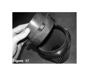
The composite velocity stack is now pressed into the filter neck and the clamp tightened.
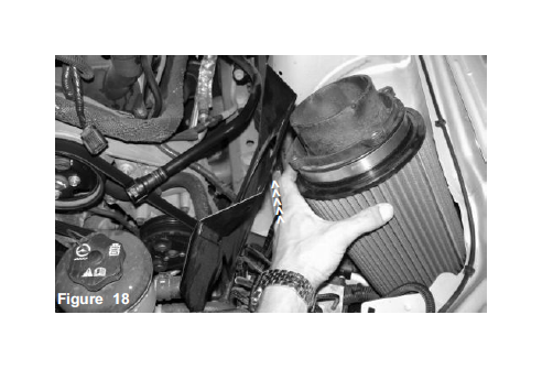
The assembled filter and velocity stack is now lowered into the engine compartment and the velocity stack neck is inserted into the heat shield opening,
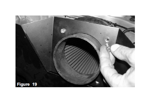
The four m6 x m12 socket head screws are used to secure the velocity stack to the heat shield. Once the velocity stack has been inserted and positioned into the heat shield, the screws will be screwed in on the reverse side.
Take the vinyl trim and press it along the top edge of the heat shield.
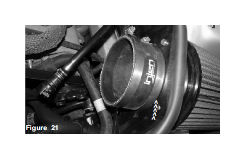
Press the 4” straight hose over the velocity stack and use two .462 Power-bands, tighten the Power-band located on the velocity stack end.
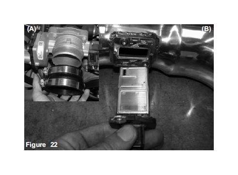
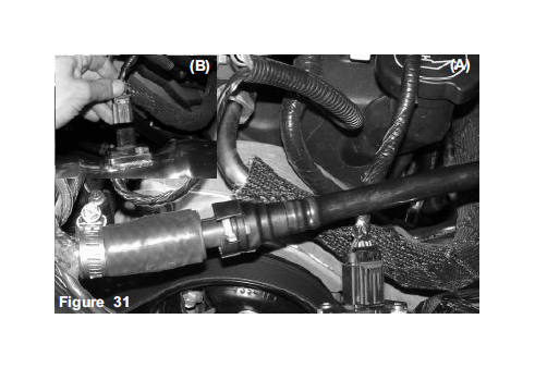
Press the molded step hose over the throttle body. Use the .362 power-band on the 3” side and the .412 power-band in the 3 1/4” side (A). The directional air flow sensor is inserted into the machined sensor adapter until the two ends are flush with each other, the stock screws are used to secure the sensor in place (B).
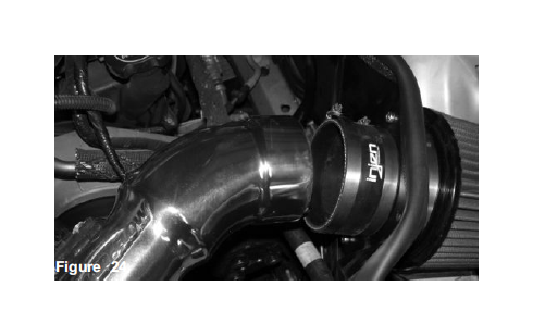
Once the step hose clamp has been tightened, continue to line up the new cast aluminum intake to the step hose and straight hose.
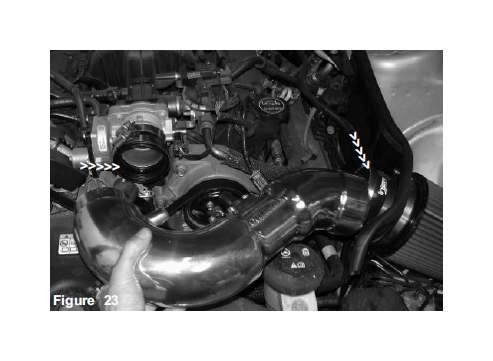
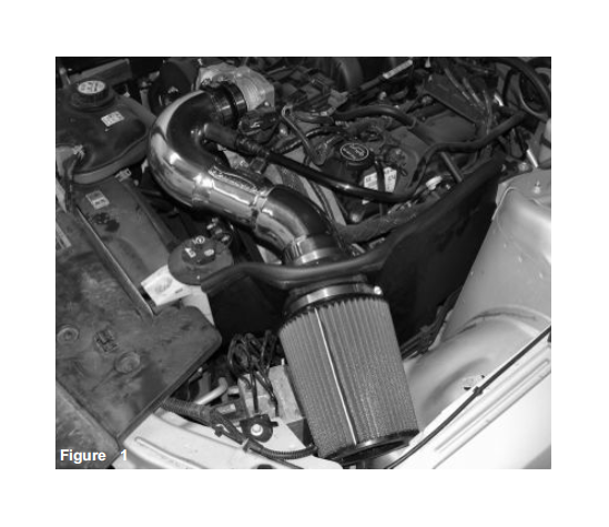
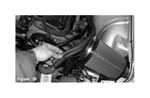
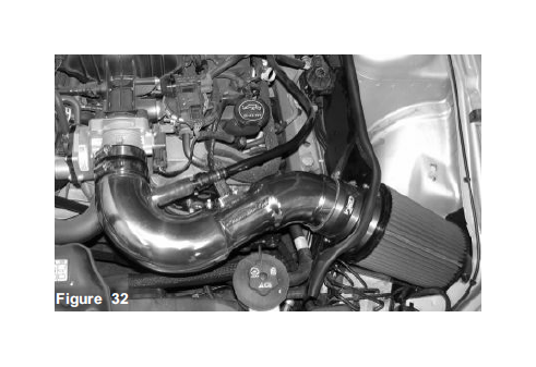
The cast aluminum intake is lowered into the engine compartment and the filter end is inserted into the 4 “ straight hose.
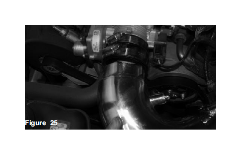
Once the filter end of the intake has been pressed into the 4” hose, the 3 1/4” end is now pressed into the throttle body step hoses shown above.
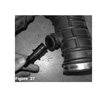
Using pliers, remove the small clamp from the air duct breather port.
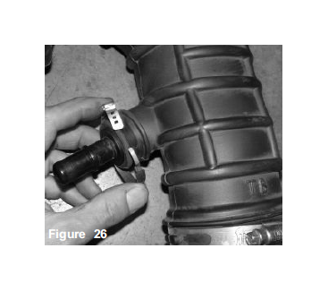
Remove the clamp and slide the plastic vacuum nipple from the air intake duct.
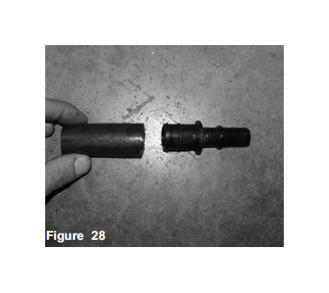
Press the 2 inch, 15.9mm vacuum hose over the 3/4” end on the molded vacuum port as shown above.
Once the 2 inch hose has been pressed over the molded vacuum port, continue to insert the vacuum port into the crank case hard pipe.
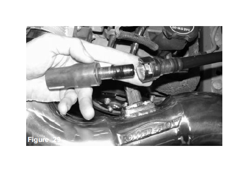
Once the vacuum port has been pressed and locked into the hard pipe breather line, continue to press the 15.9mm hose over the intake port.
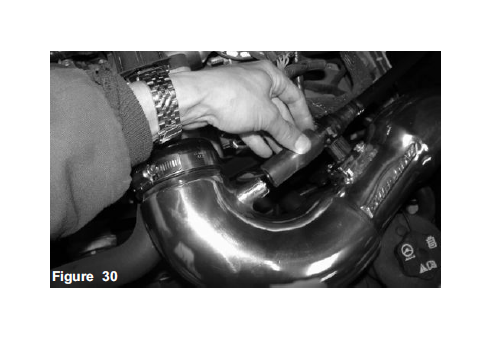
The crank case breather line is now connected to the intake port and secured with the included mini-clamp (A). Locate the MAFS harness clip and press it into the sensor, a snapping sound ensures that good contact has been achieved (B).
Congratulations! You have just completed the installation of the World’s first tuned intake system. No calibration will be required for the mass air flow sensor, the intake comes pre-tuned. Do not change the filter for any other brand, use only Injen products when cleaning or replacing filters.
1. Upon completion of the installation, reconnect the negative battery terminal before you start the engine.
2. Align the entire intake system for the best possible fit. Once the intake has been properly fitted continue to tighten all nuts, bolts and clamps.
3. Periodically, recheck the alignment of the intake system and make sure there is proper clearance around and along the length of the intake. Failure to follow proper maintenance procedures may cause damage to the intake and will void the warranty.
4. Start the engine and listen carefully for any odd noises, rattles and/or air leaks prior to taking it for a test drive. If any problems arise go back and check the vacuum lines, hoses and clamps that maybe causing leaks or rattles and correct the problem.
5. Check the filter for excessive dirt build up. Clean or replace the filter with an original Injen filter (can be bought on-line at “injenonline.com”). Congratulations! You have just completed the installation of the best intake system sold on the market. Enjoy the added power and performance of your new intake system.
