 FREE 1 to 3-Day Delivery on Orders $119+ Details
Best Sellers


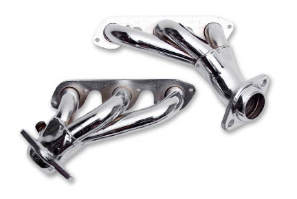
How To Install JBA Cat4Ward Shorty Headers on your 1994-1998 V6 Mustang
Installation Instructions and Warranty Information
1994-03 Ford Mustang 3.8 L V-6 Engines
1619S 1994-98 W/O A.I.R.
1619S-1 1999-04 W/O A.I.R.
1619S-3 1998 With A.I.R.
1619S-4 1999-04 With A.I.R.
CARB EO #D-57-27
Read all instructions carefully before attempting installation.
PerTronix© thanks you for choosing JBA Headers, the best fitting, highest quality header on the mar- ket. In order to realize the full potential of our good fit, please read and understand these instructions completely prior to starting work.
Check to make sure you received the proper parts for your application. The header number will be stamped on the engine flange. If you are unsure you have received the proper parts call before you start work.
NOTE: Installation of this product requires an adequate workspace, general mechanic’s tools, general me- chanical “know-how” and a reasonable degree of experience. Most auto enthusiasts with these resources will have little difficulty installing these headers. However, you should carefully read these instructions before attempting to install these headers. If in doubt, consult a professional mechanic. (Better to do it now than to get stuck halfway through the installation.)
By installing your JBA Performance Exhaust product, you indicate that you have read this document and agree with the following terms. The Purchaser is responsible for following all installation instructions and safety guidelines supplied with JBA Performance Exhaust products.
PerTronix© assumes no responsibility for damages resulting from improper operation, misuse, abuse, or lack of responsible care, or any problems resulting from incompatibility with other manufacturer’s products.
Included with your installation instructions is a copy of the product warranty. Please read it carefully before you begin any work on your vehicle.
Be sure to work safe! Whenever you work under the vehicle be sure that it is located on level, solid ground and is supported by adequate safety stands! Remember: Hot asphalt will not support most jack stands!
Many factors affect the installation of headers, some of which are broken or aftermarket motor mounts, ac- cidents that impact the configuration of the frame, and/or the installation of different engines or aftermarket cylinder heads.
Customers breaking in new engines: Due to the extreme heat generated during the break-in process, the ap- pearance of the ceramic coating may be altered in certain areas. The protection characteristics and thermal barrier properties of the coating is never compromised. It is recommended that a cast iron manifold or old set of headers be used for this process.
Notice: The coating of these headers can be marred or scratched during installation. If the header needs to be returned and is damaged, you will be charged for recoat.
JBA uses sealing beads on all its headers. We have found that when installed correctly, the raised bead around each port increases the pressure exerted on the gasket directly adjacent to the port and effectively prevents leaking gaskets. It is important when installing the header, to install all bolts loosely, then tighten evenly to ensure the flat installation of the flange. It is normal for the flange to be raised off the cylinder head the thick- ness of the sealing bead.
To prevent leakage, it is important to tighten the flanges on any set of JBA headers carefully by using the proper procedure. The torque sequence from one flange to another will vary, but generally every bolt on a header should be first fit snug, starting from the inside of the flange working out, alternating from top to bot- tom so that the bolt connects the flange to the manifold to the point where they barely touch. Second, using the same inside-out pattern, tighten each bolt until finished. This method will help prevent leakage and will give the user the best possible performance out of their pair of headers.
INSTALLATION INSTRUCTIONS:
1. Place vehicle in a location where the floor is solid and flat, with adequate lighting. Do not attempt to work on a hot engine. Heat causes metal to expand and makes removal of fasteners difficult at best. Disconnect the nega- tive battery cable from the battery. Raise the front of the vehicle to obtain adequate access to the bottom exhaust manifold flanges. Use large-basejack stands to support the vehicle. Do not rely on the jack! Block the tires to prevent the vehicle from rolling off the jackstands.
2. Apply penetrating oil on all accessible fasteners and fittings before attempting to remove them.
3. From underneath the vehicle, loosen the bolts connecting the exhaust system to the exhaust manifolds. Move the exhaust system back about 1/2 ”to gain work space.
4. On air injected models (P/N 1619), from above, loosen the air tubes at the outside of both driver and passen-ger side manifolds.
5. Remove the Oil Dipstick. It has a separate mounting bolt on the head and uses an O-ring seal at the bottom.
6. On the driver’s side, remove the fasteners attaching the manifold to the head and remove the manifold.
7. On the passenger side, remove the fasteners attaching the manifold to the head then remove the manifold.
8. Remove the gaskets and any gasket material or any carbon deposits that remain on the head surface. The use of a gasket removal agent will ease the removal of any gasket material. Use care not to get debris into ports or spark plug holes.
Driver’s Side Header
1. Start the air injection tube nut on the driver’s side header before you start the header bolts.
2. Slip the dipstick through the driver’s side header and into the block before bolting the header to the head.
3. Slip the Header Gasket between the header and the head and install using the supplied header bolts and lock washers. Apply Anti Sieze to the bolts before installing ans torue evenly to 13 ft./lb.
Passenger Side Header
1. Start the EGR tube and the Air Injection Tube on the passenger side header before you start the header bolts.
2. Slip the Header Gasket between the header and the head and install using the supplied headers bolts and lock washers. Apply Anti Sieze to the bolts before installing ans torue evenly to 13 ft./lb.
3. Apply a light coating od Sensor Safe Hi Temp Silicone on the Header collector domes and connect the ex- haust system to the new headers using the hardware provided.
4. Check that all bolts are tight. Make sure that all wiring, fuel lines, transmissions lines, brake lines etc are clear of the headers and the exhaust and relocate as necessary.
5. Reconnect the negative battery cable.
6. Start the engine, check for leaks and test drive. Then let engine cool and then re-torque the header bolts.
7. Periodically check and retighten the header bolts.
LIMITED ONE YEAR WARRANTY
All JBA HEADERS and exhaust products are guaranteed, to the original purchas- er, to be free of defects in materials and workmanship for one year. This warranty covers the replacement or repair of the product only and does not cover the cost of removal and installation, customer applied aftermarket coatings or any discolor- ation or corrosion of finished surfaces.
Damage or product failure resulting from collision, improper installation, off-road use, road hazards, the use of exhaust insulating wrap or like products or rust oc- curring after installation, is not covered by the warranty. The warranty extends only to the original purchaser.
Should a part become defective it should be returned to the original selling retailer and must be accompanied with the sales receipt. If there is no retailer in your area, call the factory for a return authorization and return your part prepaid to the factory for inspection. PerTronix reserves the rights to replace or repair the alleged defec- tive part and return the part freight collect.
