 FREE 1 to 3-Day Delivery on Orders $119+ Details
Best Sellers


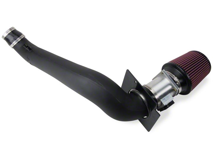
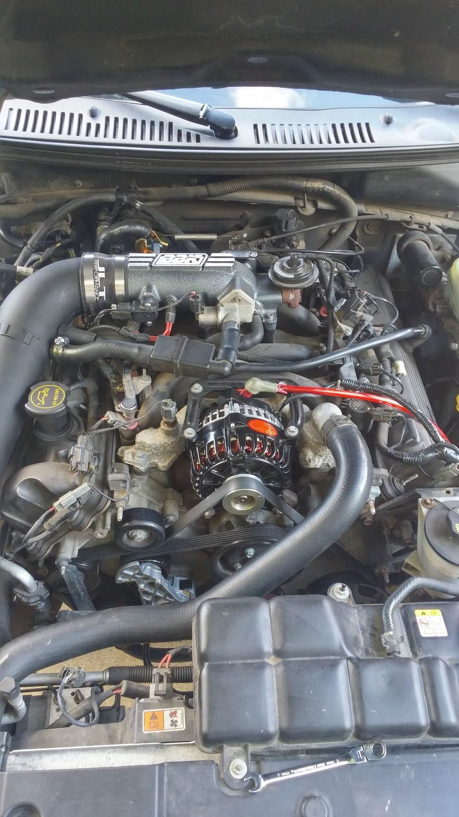
How to Install a Performance Next Generation Mustang Cold Air Intake on your 1996-2004 GT Mustang
Installation Time
1 hours
Tools Required
- 8mm socket/ratchet or open end wrench
- 10mm socket/ratchet or open end wrench
- 11mm socket/ratchet or open end wrench
- Phillips head screwdriver
- Regular screwdriver
- Car jack
- Jack stands
Shop Parts in this Guide
Special note for 1996- mid 2001 Mustang Installations:
For these model years, the Mustang MAF sensors included a separate intake air temperature (IAT) sensor. In order to account for this sensor, a 3/4” hole needs to be drilled into the intake tube. The hole should be drilled using a stepped drill bit, and should be approximately 13” from the end of the intake tube with the JLT logo on the bottom side. Install the included grommet in the drilled hole. PULL the IAT sensor from the stock inlet and install the IAT in the grommet.
Installation Instructions:
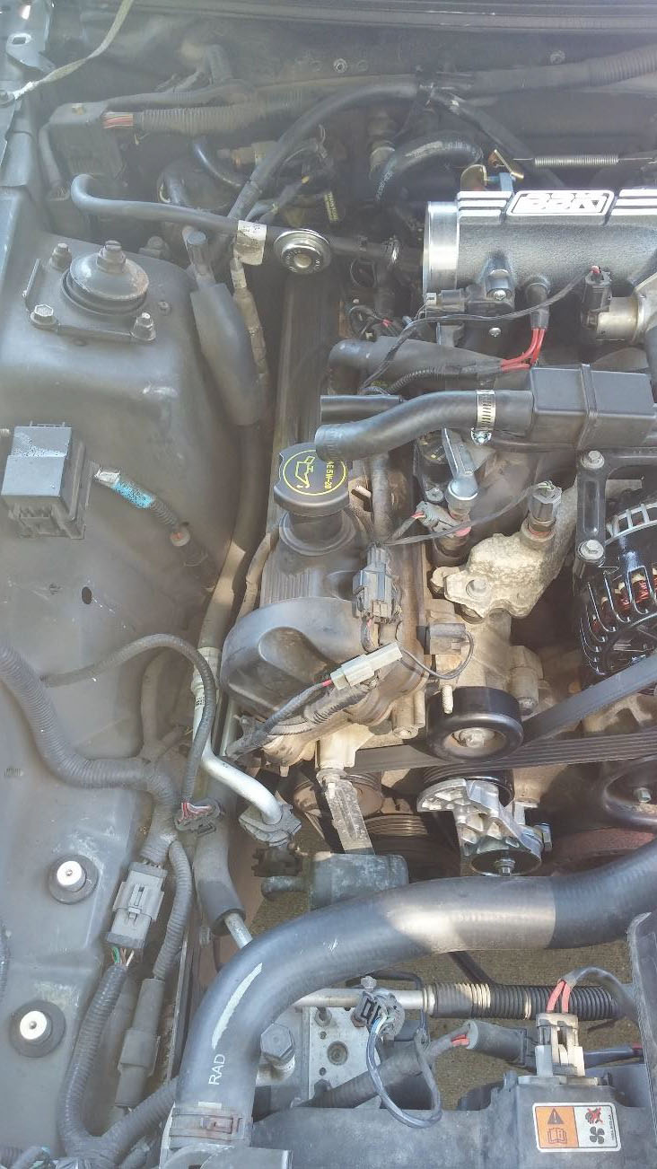
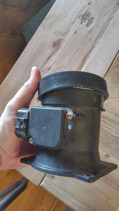
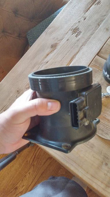
1. Depending on your current set-up, you may or may not have an aftermarket intake on your Mustang. In order to provide the most concise instructions possible, this guide will outline only the installation instructions for the JLT Performance Cold Air Intake. Remove the air intake system from the throttle body to the filter housing. Various guides are available through American Muscle or other websites and forums detailing removal of the stock air intake and other cold air intakes. The important item you will need from your previous set-up is the MAF (mass air flow) housing. To remove the housing, simply unplug the MAF sensor from the MAF wiring harness that is attached to your Mustang.
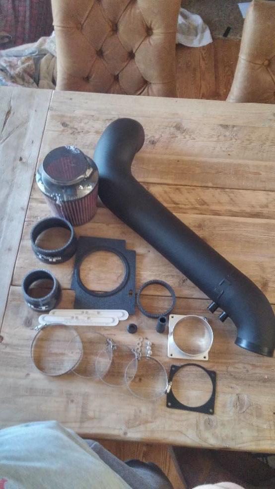
2. First, gather all of the parts that came in the box. Notice that there are several different hose clamps, two different rubber air reducers, a rubber spacer, four bolts and washers, an aluminum MAF spacer and gasket, a hose fitting, a splash plate, a rubber grommet, a pre-packaged air filter and hose clamp, the intake tube, and a few JLT stickers. Note, the grommet is only used when adding the IAT sensor.
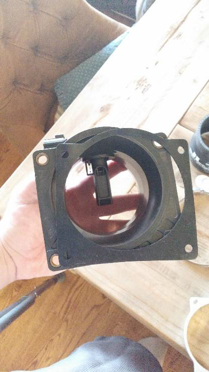
3. With the MAF housing in hand, place the rubber spacer over the non-flanged end of the MAF housing.
4. Next, line-up the gasket with the holes on the flanged side of the MAF housing.
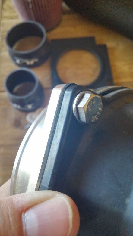
5. Line-up the aluminum MAF spacer with the gasket. Place the washers over the bolts, and thread the bolts from the MAF housing to the aluminum MAF spacer. Be careful not to over-tighten these bolts as the plastic MAF housing is prone to cracking. These bolts are 11mm, and should be tightened using a socket and ratchet or wrench.
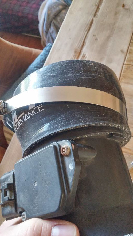
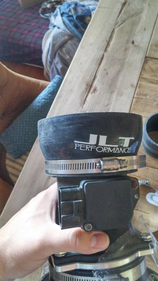
6. Next, place the large rubber reducer over the spacer on the MAF assembly. Use a hose clamp to secure the reducer to the MAF assembly. Note, the hose clamp to be used in this step is the second largest hose clamp. Tighten down the hose clamp loosely. Only tighten the hose clamp enough to secure the reducer to the MAF assembly. The hose clamps can be tightened using a Phillips or regular screwdriver. For most applications, the ideal tool is a short “stubby” regular screw driver with a medium width head.
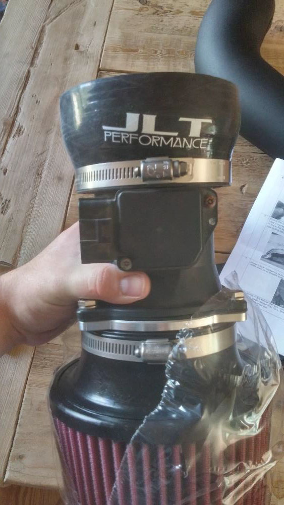
7. Next, open up the air filter assembly. Keep the plastic over the air filter if possible, removing only enough plastic to attach the air filter to the MAF assembly. Using the included hose clamp and a screw driver, secure the air filter to the MAF assembly. Be careful not to damage the air filter during installation. Bending the fins on the air filter will cause decreased performance of the filter when in use.
8. Next, take the intake tube and attach the other (smaller) reducer to the intake tube using a hose clamp.
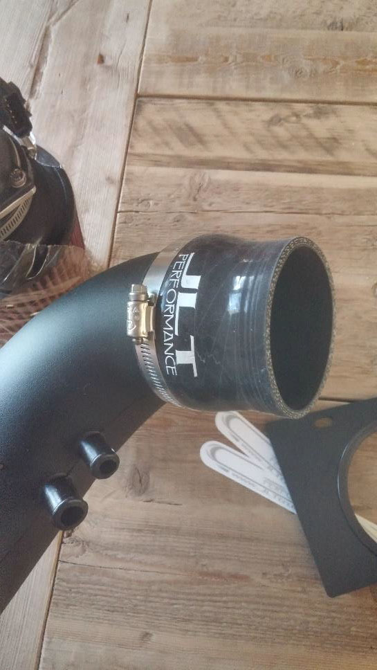
9. Place the hose fitting over the smaller fitting on the intake tube.
10. Due to the large size of the intake tube, it is necessary to remove the large wire harness hold-down that MAF wires are held into. Next, feed the MAF wires through the splash plate (note that you only need a few inches of wire fed through the splash plate). The most convenient place to feed the MAF wires is through the circular opening in the splash plate under the intake tube.
11. Place some tape over the large hole in the splash plate. This tape will protect the intake tube from the edges of the large hole causing unintentional scratches on the intake tube.
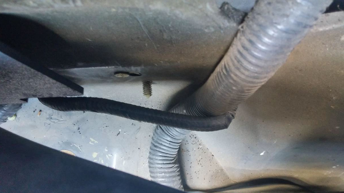
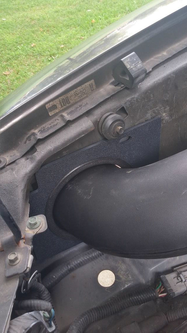
12. Install the splash plate into the engine bay by tightening the small bolt through the small hole in the top of the splash plate and into the small receiver in the engine bay. Notice that if this bolt includes a rubber spacer on it, the rubber spacer will not be needed. This bolt is an 8mm bolt. Insert the intake tube into the splash plate and rotate the tube so that the intake tube is properly aligned.
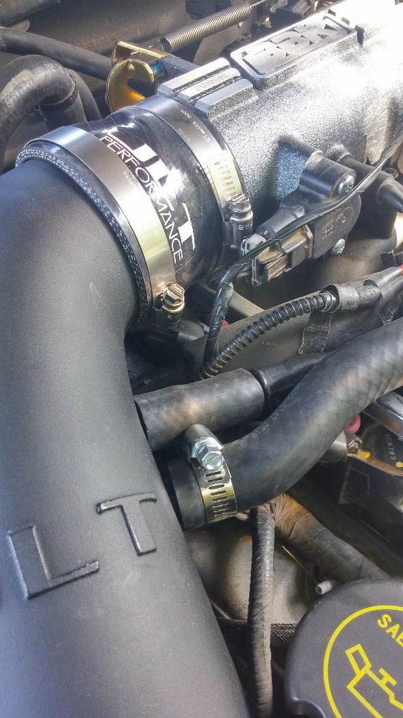
13. Attach the reducer on the top end of the intake tube, the end with the JLT logo, to the throttle body. Tighten down the hose clamp to secure the reducer to the throttle body. Again, use the screwdriver for this process.
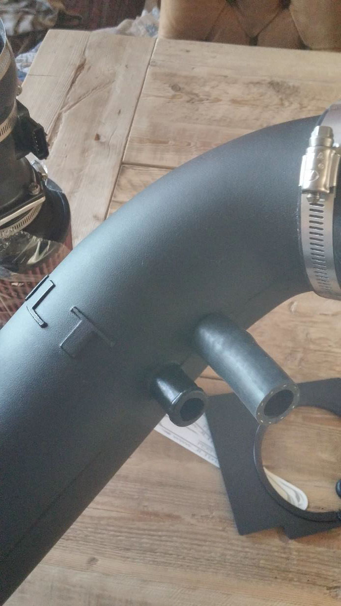
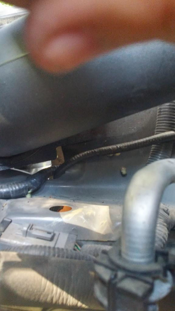
14. Next, attach the two small tubes to the side of the intake tube. Note that connecting these tubes may cause their corresponding connections to be come loose. For this reason, after connecting these tubes to the intake tube, check to make sure that both tubes are completely connected at all connections. Using a small hose clamp as pictures may help secure the small hoses to the intake tube.
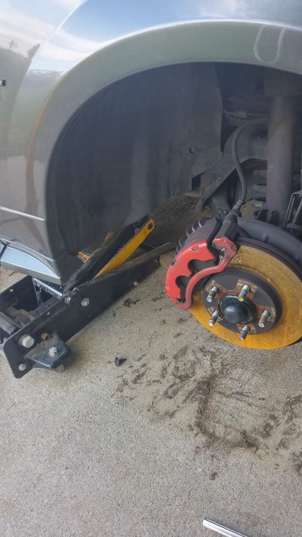
15. Jack up the car using a jack and support the car with jack stands. You will need to remove the front, passenger wheel.
16. Remove the front passenger wheel.
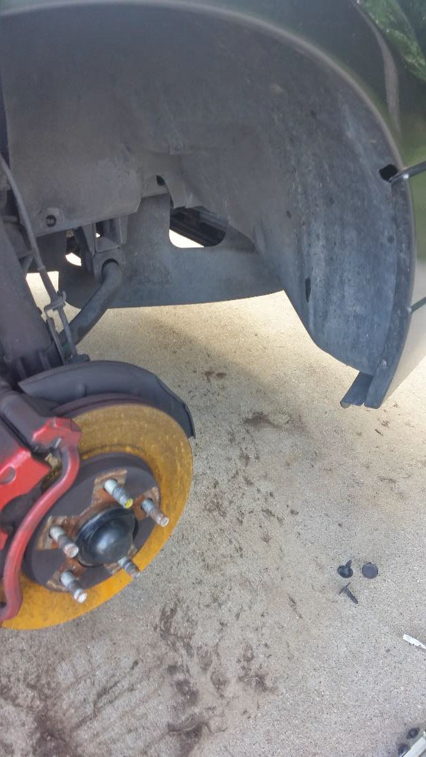
17. Remove the inner wheel well. The inner wheel well behind the passenger front tire is held on by removable pins that can be removed with a regular screw driver. The inner wheel well is also held in by a few Phillips head screws.
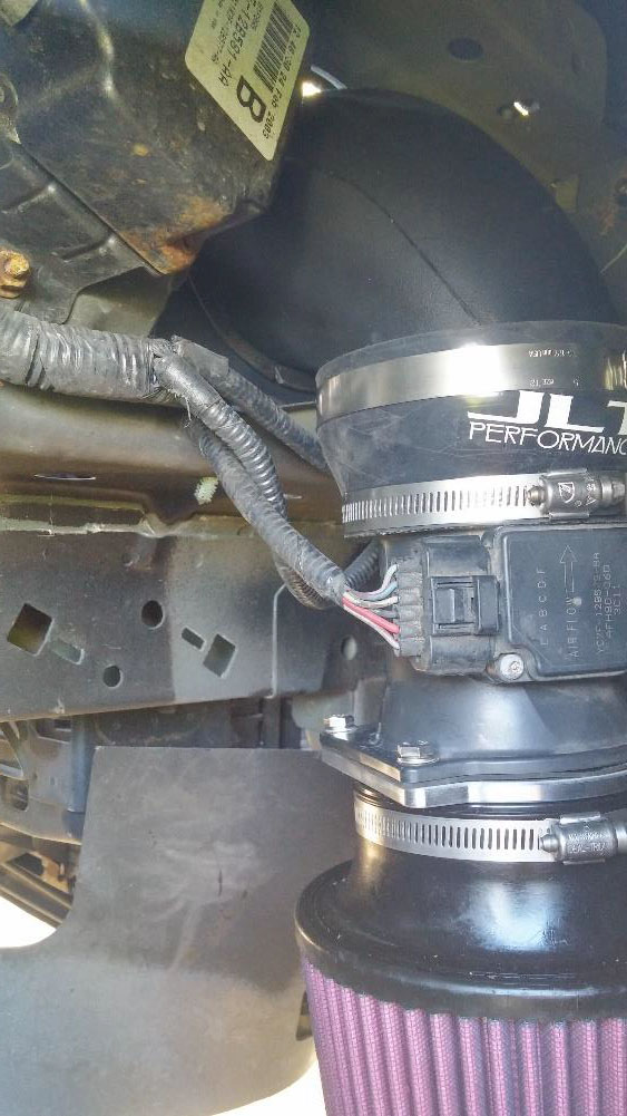
18. Insert the air filter assembly into the wheel well. Secure the air filter assembly to the intake tube by using a hose clamp. The MAF sensor should be positioned such that the exposed electrical prongs point towards the rear of the vehicle.
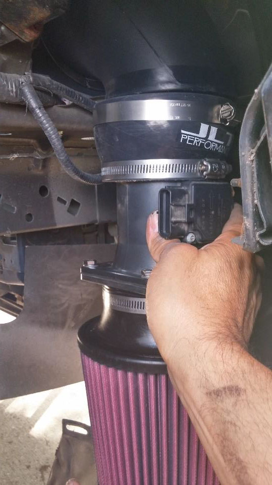
19. Connect the MAF sensor to the MAF sensor wiring harness.
20. Replace the inner wheel well by reinserting the removable pins and screws.
21. Replace the wheel, remove the jack stands, and lower the vehicle off of the jack.
22. Congratulations, your new JLT cold air intake is successfully installed!
23. Note: If you own a tuner such as the Bama tunes offered by American Muscle, it is not necessary but may be advantageous to retune your Mustang. The JLT cold air intake provides a sizeable increase in power compared to other kits available. Also, it may be wise to reset your Mustang’s Keep Alive Memory (KAM). This can be done through various tuners or other processes published online.
Installation instructions written by AmericanMuscle customer Roberto Fernandez on August 21st, 2015.
