FREE 1 to 3-Day Delivery on Orders $119+ Details
Best Sellers


How To Install a JMS Fuelmax - Fuel Pump Voltage Booster V2 on your 2015-2016 Mustang
Installation Time
1.5 hours
Tools Required
- Multimeter
- Wire Strippers
- Plastic Cable Ties
- Electrical Tape
- Soldering Iron/Gun (optional)
Shop Parts in this Guide
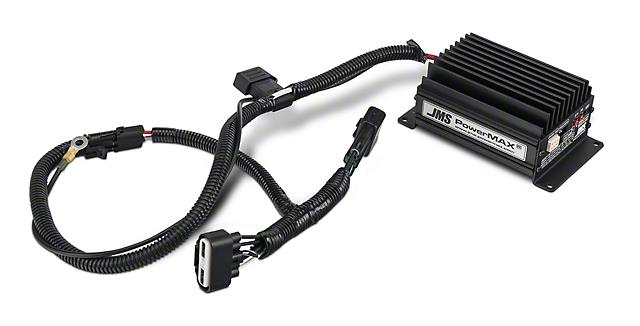
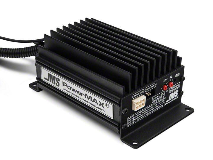
(image of Booster Unit from American Muscle website.)
**IMPORTANT NOTE**
This kit comes with an adapter to be plugged into the accelerator pedal, but does not work for the 2005- 2010 mustangs. A Hobbs pressure switch is supposed to be used with this setup, which can be acquired directly from www.jmschip.com. However, this guide shows how to wire into the throttle position sensor (TPS) instead, making this installation similar to that for the accelerator pedal.
* A second person is needed to work the accelerator pedal for testing.
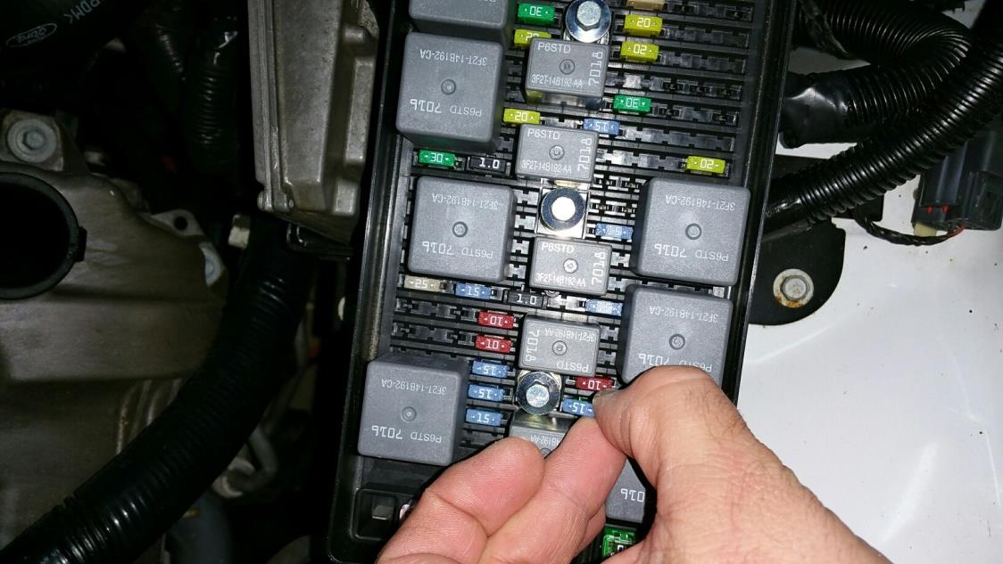
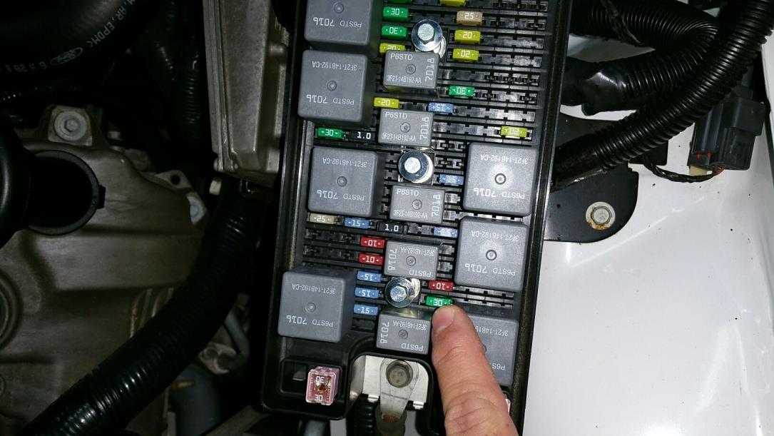
STEP 1:
Remove the 15 amp fuse in the engine compartment fuse block to disconnect the power to the fuel pump. (Note that this fuse will need to be upgraded anyway to a larger 30 amp fuse later on.)
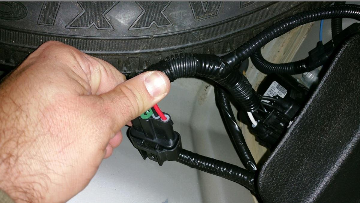
STEP 2:
Remove the truck panels and open the spare tire compartment to access the factory plugs for the fuel pump.
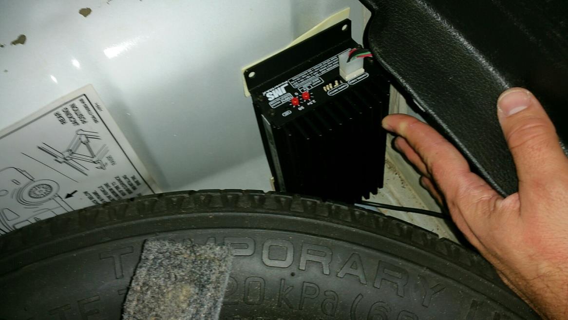
STEP 4:
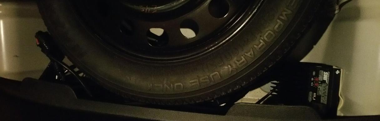
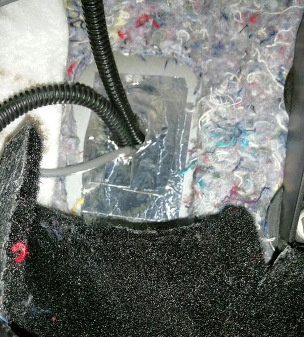
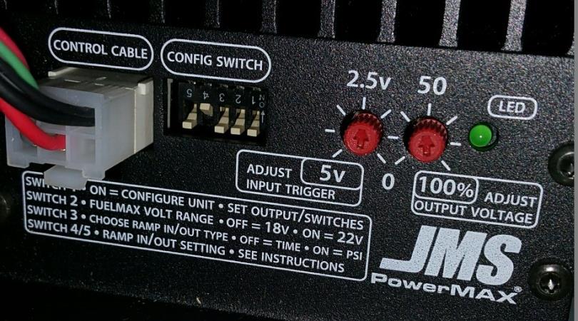
Install the voltage booster unit somewhere in the trunk with the setting dials in a visible and accessible orientation. Secure the unit in place with bolts or screws. (I had installed mine in the spare tire compartment since I know that regular access to this unit is not needed, and had temporarily utilized very strong double-sided tape since I had no concern of this unit moving around in this confined compartment. Once I know I am happy with this location, I will mount this unit permanently with screws.)
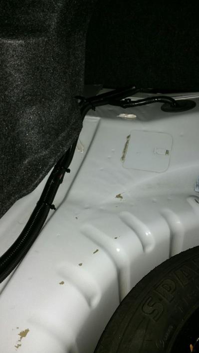
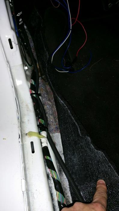
STEP 5:
Run the cable along the driver side of the car, under the interior panels and door sill. Fasten with plastic cable ties along the cable length to keep the installation neat and clean.
STEP 6:
Run the cable through the firewall. (Note that automatic cars can run this cable through the unused factory opening intended for a manual transmission clutch assembly.)
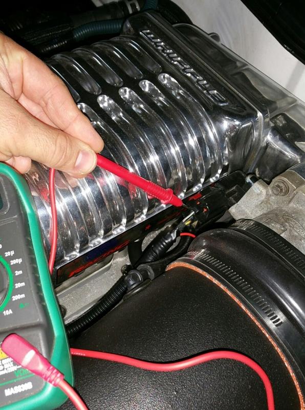
STEP 7:
Locate the wires for the throttle position directly wired into the throttle body. Using the multimeter, check the wires to see which one has varying voltage when the accelerator pedal is pressed (by someone else in the car).
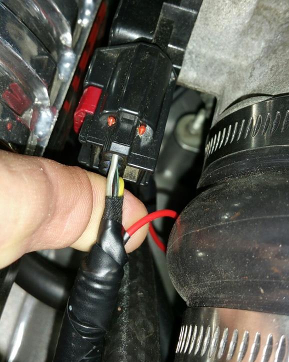
STEP 8:
First disconnect the battery. Then strip approximately 1⁄2 inch of sheathing off the wire, trying not to cut the wire itself. Wrap the wire around the newly stripped wire. (**OPTIONAL** You can solder this connection to make sure this connection to make this connection more permanent.) Wrap the connection with electrical tape.
STEP 9:
Install cable ties along the wire within the engine compartment for a neat, clean installation.
STEP 10:
Install the larger 30 amp fuse in the fuse block from which the 15 amp fuse was earlier removed.
STEP 11:
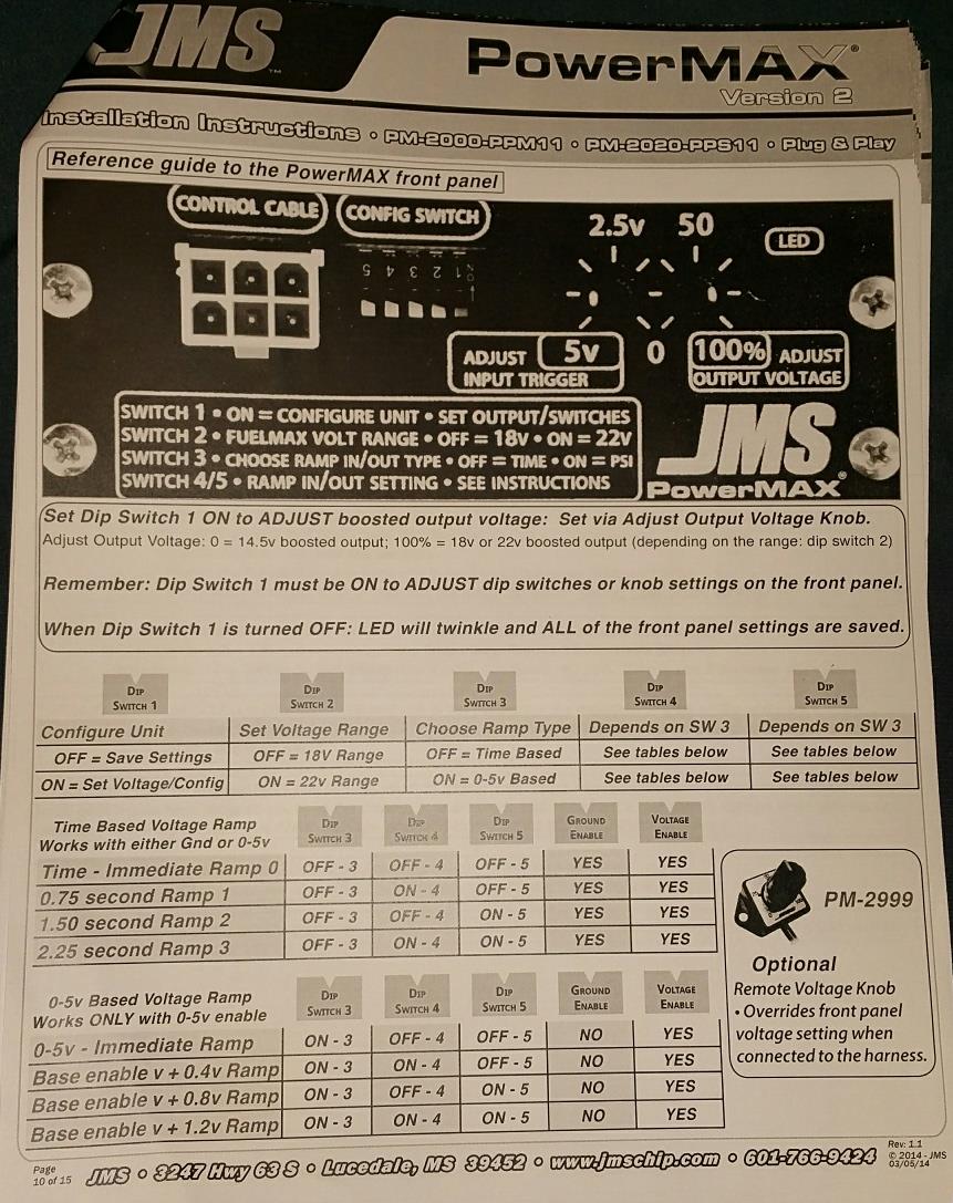
Reconnect the battery. Make adjustments to the booster settings as indicated in the fuel voltage booster setup guide. (I had set my fuel voltage booster to activate on “Time Based Voltage Ramp” with 0.75 second ramp. You may want to consult with your tuning specialist for a setting most appropriate for your car.)
STEP 12:
Have someone turn the key on (but do not start the car) to test the voltage booster unit while you view the indication lights on the booster unit. With the key on, the light should turn solid (not blinking) indicating that the unit is on and receiving power.
STEP 13:
Set the trigger point at which the booster unit will activate by adjusting the left dial. (The pedal registers 5 volts at full throttle, so at a 2.5 volt trigger point, the booster will activate at 1⁄2 throttle.) Once this is set, have the individual depress the accelerator pedal very slowly and you should note when the light starts to blink, indicating that the booster unit is operating. Have the individual tell you the status of the accelerator pedal as they press it. (They should tell you when it is 1⁄4 down, 1⁄2 down, 3⁄4 down, and all the way depressed.) As a double check, have the individual slowly lift off the accelerator pedal so you can verify the pedal position when the booster unit is no longer activated.
STEP 13:
Set the right dial to the amount of voltage increase you want for the fuel delivery. (This ultimately dictates how much fuel will be delivered during the booster pump operation.)
STEP 14:
Reinstall the tire compartment cover and all other removed trunk panels and any other interior panels. Test drive the car to check its fuel delivery and be sure the car doesn’t run lean at hard acceleration and at WOT. (A fuel gauge is very helpful for this, however, an A/F gauge will work as well.) You may need to readjust the voltage booster unit for the desired performance.
STEP 15:
Re-access the fuel pump booster unit and secure it permanently in-place. If desired, relocate the booster unit to another place and then secure it in-place.