FREE 1 to 3-Day Delivery on Orders $119+ Details
Best Sellers


How to install Maximum Motorsports Caster Camber Plates on your Mustang
Shop Parts in this Guide
Installation
Read all instructions before beginning work. Following instructions in the proper sequence will ensure the best and easiest installation.
Thank you for purchasing Maximum Motorsports’ Caster/ Camber Plates. Our Caster/Camber Plates are designed to maximize the performance of your Mustang’s front suspension. You will find many features that set our Caster/Camber Plates apart from the rest:
- The widest range of camber adjustment in the industry: Side-to-side reversible bearing plates double the camber adjustment with the underhood space limitations for camber slot length.
- Lifetime guaranteed high grade Teflon® lined spherical bearings are used at the strut top mounting point. Urethane bushings do not provide positive location, and induce bending loads on the strut that reduce the strut’s lifespan and may even break the strut shaft.
- The main plates are spaced above the strut tower, while maintaining good hood clearance, to restore bump travel for lowered cars.
- Our unique design places the bearing cup on top of the main plate, further maximizing precious bump travel with the low hoodline of 94 cars. Bearing plates placed under the main plate typically have 1/2” less bump travel than our configuration.
- High grade alloy steel allows our plates to be thin and fatigue proof. Aluminum plates must be very thick and will un-necessarily reduce bump travel and hood clearance.
- Patented 4 bolt X 4 bolt configuration. This means that 4 bolts secure the bearing plate to evenly spread the load into the main plate. 4 bolts also secure the main plate to the car’s strut tower to eliminate strut tower bending.
- Lifetime warranty against main plate bending.
IMPORTANT: The bearing used in our Caster/Camber Plates is swaged together with Teflon® in between the race and ball. This provides a very tight tolerance fit that prevents dirt from entering the bearing. The Teflon® reduces friction and minimizes wear over the lifespan of the bearing. The tight tolerances will not allow easy movement of the bearing center by hand. If the center of the bearing must be rotated, use the strut shaft as a lever to facilitate movement. DO NOT ATTEMPT TO LUBRICATE THE BEARING. Any oil or grease will attract dirt and damage the Teflon®, voiding your warranty.
1. Jack up the front of the vehicle and place firmly on jack stands.
2. Remove the front wheels.
3. On the passenger side of the car, place a floor jack under the control arm and jack up until slightly loaded.
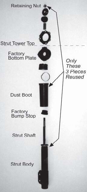
4. Remove the strut top nut. Save the strut top nut, it will be used later.
NOTE: It may be easier to initially loosen the nut with air tools.
5. Remove the three nuts/bolts that hold the factory strut mount in place. If present, drill and remove the pop rivet that retains the top mounting plate. Keep the top mounting plate handy as it will be used as a marking template for the fourth bolt hole.
6. Carefully lower the jack to bring the strut shaft down through the strut tower center hole, but do not completely unload the jack: the spring may become dislodged, causing injury and/or damage.
7. From the top of the strut tower, remove and discard the thrust washer, the top rubber bushing and the crush sleeves from the strut shaft.
8. Collapse the strut shaft down into the strut body far enough to remove the factory bottom plate and the dust boot. Discard the factory bottom plate. Save the dust boot.
9. Relax the strut shaft. Through the strut tower center hole, remove and discard the OEM bumpstop from the strut shaft.
10. Cut and remove the steel band clamp securing the plastic dust boot tube to the molded rubber/steel top mount. Seperate the dust boot tube from the rubber/ steel top mount. Discard the rubber/steel top mount, but save the dust boot tube.
11. Slip the dust boot tube back over the strut body. Lubricate the MM urethane bumpstop and slide it over the strut shaft with the conical portion facing upward. It is easiest to attach the bumpstop and the dust boot to one another later in the installation.
NOTE: The factory dust boot and MM bumpstops are NOT used in coil-over applications. If using Bilstein struts, the MM bumpstops and the factory dust boots are not used. Bilstein struts have internal bumpstops and their own dust boots. For replacement dust boots for Bilstein struts, you can order a Service-6 kit from MM for conventional spring applications, or a Service-7 kit for coil over applications.
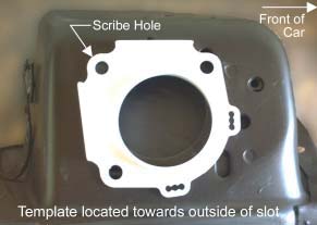
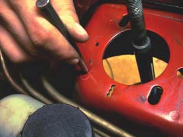
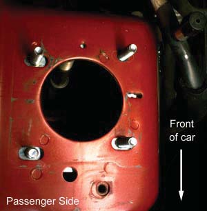
12. Now you must drill the fourth hole for the MM 4-boltbottom plate. Using the Ford top plate as a template, rotate it 180O from the stock position, aligning the holes with the inner edge of the factory slots in the strut tower. Scribe the position of the hole on the strut tower. Passenger side shown in the following photos.
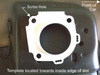
13. Slide the Ford top plate to align the holes with the outer edge of the factory slots and scribe a second hole.
14. Repeat Steps 3-13 for the driver side of the car. You may now discard the Ford top plates.
15. On each side of the car, locate the intersection of the 2 holes you marked on the strut towers and centerpunch this spot. Driver side shown in the following photos.
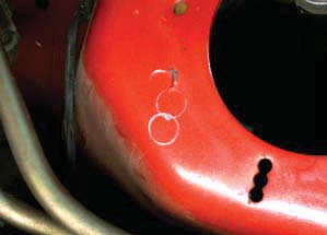
16. On each side of the car, drill an 1/8” pilot hole on the center-punched mark. Then drill the 1/8” hole to 13/32". Debur the top and bottom of the hole.
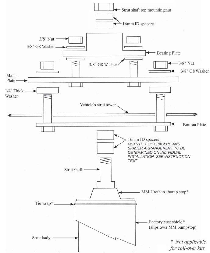
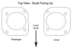
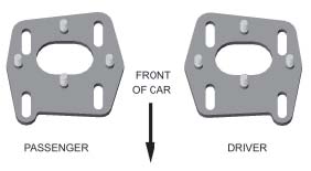
17. On the passenger side, install the MM bottom plate beneath the strut tower with the 3/8" bolts protruding upwards. Use the Illustration below to select and orient the bottom plates correctly.
TIP: It may be helpful to use silicone adhesive to stick the bottom plate to the underside of the strut tower.
18. Install a 1/4" thick washer over each bottom plate stud. The thick washers will rest directly on top of the strut tower.
19. Place the passenger side main plate over the bottom plate’s studs, and on top of the 1/4” thick washers. Install a 3/8” washer followed by a hex nut on each of the bottom plate’s studs. Use the illustration below to select and orient the main plates correctly.
20. Repeat Steps 17-19 for the driver side of the car.
21. On each side of the car, place a 3/8" washer over each of the four studs protruding out of the Main Plate.
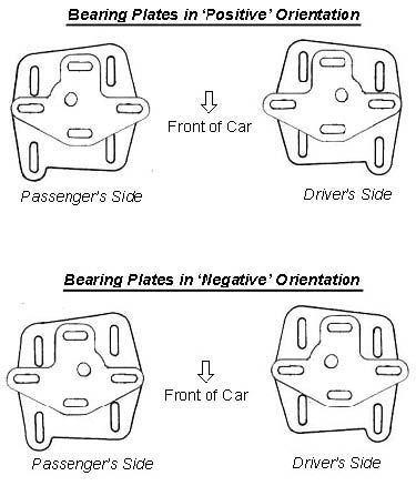
22. Install the Bearing Plate over the washers on top of the Main Plate, followed by a washer and hex nut on each stud.
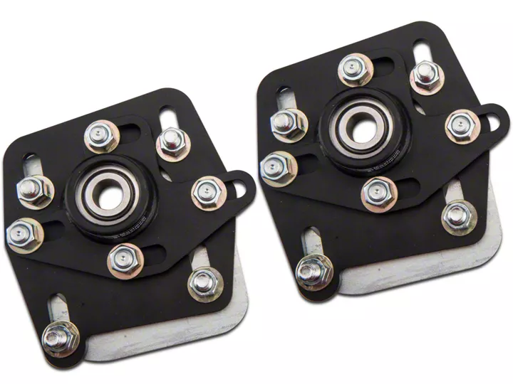
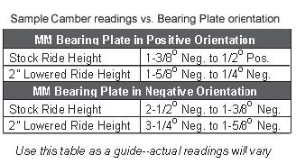
NOTE: The orientation of the Bearing Plate can be either ‘positive’ or ‘negative’. Use the following illustration to properly position the Bearing Plates on the Main Plates. Use the table as a guide to determine the orientation of the Bearing Plates for your alignment needs. The majority of street cars will have the Bearing Plates installed in the ‘positive’ orientation. The majority of race cars will have the Bearing Plates installed in the ‘negative’ orientation. To change the Bearing Plates between positive and negative orientation, swap the Bearing Plates to the opposite sides of the car. For example, a bearing plate on the driver’s side in the positive orientation will be in the negative orientation on the passenger side.
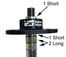
23. Install the strut shaft through the spherical bearing of the caster camber plates with four of the supplied 16mm inside diameter spacers per side (two short and two long). Use the guidelines below to determine the correct combination of spacers to put above and below the spherical bearing. Use the same spacer configuration on each side of the car.
NOTE: For MM Coil Over applications, consult your Coil-Over Instructions for correct spacer arrangement.
Important - At least one spacer above the caster camber plate spherical bearing is required to allow proper movement. Failure to do so will result in limited bearing articulation and possible damage to the bearing and/or the strut!
For cars at stock ride height:
- Install 2 long spacers and 1 short spacer below the spherical bearing. Install 1 short spacer above the spherical bearing. There should be a total of 4 spacers per side.
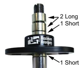
For lowered cars:
- If using any of the Tokico 3026 series of struts, use the spacer guideline above for vehicles at stock ride height. Failure to do so will severely limit droop travel and may contribute to unsafe driving conditions.
- For all other struts, install 1 short spacer below the spherical bearing. Install 2 long and 1 short spacer above the spherical bearing. There should be a total of 4 spacers per side.
Carefully close the hood to check for interference between the top of the strut shaft and the hood. You can check hood clearance by carefully closing the hood with putty or Play Dough on top of the strut shaft. The thickness of the smashed putty will indicate exactly how much hood clearance there is. If hood clearance is less than 1/8”, reposition the strut shaft spacers to lower the strut shaft relative to the spherical bearing. If the hood hits the strut shaft, rearrange the spacers to lower the strut shaft. This can be accomplished by moving a spacer from above the bearing to below the bearing, thus making the spacer stack below the bearing taller. Repeat this process until there is adequate hood to strut shaft clearance. Remember that the hood to strut shaft clearance will change after the alignment is set. Re-check this hood clearance after your Mustang is aligned!
24. Reinstall the strut shaft top mounting nuts. Torque the nuts to your strut manufacturer’s specification. NOTE: Various strut manufacturers have unique lengths for the top threaded portion of the strut shaft. You may need to omit a spacer to fully engage the nut on the strut shaft.
25. Temporarily tighten the Caster/Camber Plate adjusting nuts: Four 3/8” nuts for caster and four 3/8” nuts for camber.
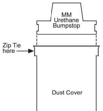
26. Slide the MM urethane bumpstop up as far as it will go. Slip the dust boot up and onto the bumpstop. Secure it with a Zip Tie.
27. Pull the bumpstop/dustboot down the strut shaft slightly so that it will not interfere with the sliding portions of the Caster/Camber Plates while the alignment is being performed.
28. Reinstall the front wheels and carefully lower the vehicle to the ground.
29. Torque the lug nuts to the factory specification.
30. Have your car professionally aligned.
NOTE: Because camber and caster can be adjusted independently with the MM plates, you can adjust one, lock it down, and then adjust the other. Always double check all camber and caster measurements after an adjustment of even one parameter. Remember that any time you make any change in camber, caster, or ride height, you must re-adjust the toe setting.
31. Ford’s production tolerances on the position of the large center hole of the strut tower can cause interference when the camber or caster is adjusted towards the limit of travel. If you are adjusting towards the extreme limits of camber and/or caster, check the clearance between the strut shaft and the edge of the large center hole. Check not only with the wheels pointed straight ahead, but also while turning the steering from lock to lock. You may enlarge the center hole with a file or die grinder.
32. Caster and camber settings change the strut shaft’s position relative to the hood. Double check hood clearance with the car on the ground, while turning the steering from lock to lock. If necessary, reposition the strut shaft spacers to lower the strut shaft relative to the spherical bearing.
33. When the alignment is complete, torque all the caster camber plate adjusting nuts to 32 ft-lb.
ALIGNMENT RECCOMENDATIONS
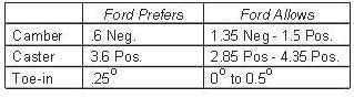
If you wish, you can simply have your car aligned to Ford’s specifications:
We recommend that caster be set to 4.5 degrees positive for street cars - but do not adjust the plate beyond the halfway point without special attention to bumpsteer detailed below. For race cars we recommend that the caster be set to 6.5 degrees positive, or at the limit of adjustment on the plate - with mandatory attention to bumpsteer. The Mustang responds favorably to increased positive caster. The reason: The more positive the caster setting, the more negative camber the loaded tire will gain while cornering.
We recommend that camber be set to .5 degree negative for street cars, never positive as Ford allows. For race cars we recommend 1.5 to 2.5 degrees negative camber. Some cars/drivers need more negative camber for optimum handling and tire wear. Keep an eye on your own tire wear and make adjustments as necessary. We recommend setting the toe to the factory spec of .5 degree toe-in for street use. For race cars we recommend .5 degree toe-out.
BUMPSTEER
Bumpsteer is the toe setting of a wheel changing as the suspension moves up and down over bumps, or with body roll while cornering.
There is a myth that the tie rod should be kept parallel to the ground to avoid bumpsteer. THIS IS NOT TRUE! What IS required, is that the tie rod be kept parallel to the lower control arm so that as the suspension moves, the arc of the ball joint and the arc of the tie rod end do not cause any steering input to the spindle. As you lower your car, the tie rod end and the lower control arm move together, staying parallel. If you install offset rack bushings on a stock geometry K-member, you are making the tie rod end and the lower control arm NOT parallel. You will actually CREATE bumpsteer by installing offset rack bushings on a stock K-member.
Ford engineers have actually done a very good job at designing a low level of bumpsteer for daily driven cars. Specifically, Ford has designed the bumpsteer to toe out the front wheels under bump. This is a roll understeer condition; the outside loaded tire will turn to the outside of a corner as the body rolls. This condition is designed by Ford by positioning the tie rod end slightly low relative to the steering rack. Increasing caster raises the tie rod end relative to the steering rack. Increasing caster up to half of the adjustment range with our Caster/Camber Plates will actually HELP bumpsteer and help performance by reducing roll understeer. If you increase caster beyond half of the adjustment range, the bumpsteer curve will shift toward toe IN under bump, or a roll-oversteer condition. In this case, it is beneficial to raise the rack, but only by about 1/10 of an inch. Offset rack bushings raise the rack far too much. The best solution is to lower the tie rod end using a bumpsteer kit (MMTR-3,-4). See our test results in the July 1993 issue of Super Ford for details.
Competition cars using stock K-member geometry will also benefit from an adjustable tie rod end kit (MMTR- 3,-4). These kits provide an assortment of spacers in .015" increments to best position a rod end at exactly the correct height; thus taking into account suspension geometry tolerances.
Offset rack bushings DO have a purpose and may be beneficial if you have raised your inner control arm pivots using an aftermarket K-member. In this case, raising the rack will help match the geometry of the raised inner control arm pivots. If you do use offset rack bushings, be sure to only use aluminum bushings - polyurethane offset bushings do not work. The urethane has too much “give”, and therefore it is impossible to get the rack mounting bolts tight enough to prevent the bushings from rotating during hard cornering.
This kit includes:
2 Bottom Plates
2 Main Plates
2 Bearing Assemblies
8 3/8 X 1/4 thick Washers
24 3/8 G8 Washers
16 3/8 Hex Nuts
2 Polyurethane Bumpstops
2 14” UV Resistant Black Zip Ties
4 16mm ID Strut Shaft Spacers - Short
4 16mm ID Strut Shaft Spacers - Long
1 Instruction Set