 FREE 1 to 3-Day Delivery on Orders $119+ Details
Best Sellers


How to Install a McLeod Street Pro Clutch on your 1986 to Mid 2001 Mustang GT and Cobra
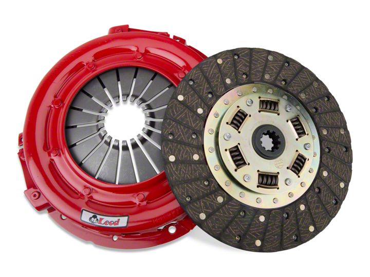
Shop Parts in this Guide
General Installation Instructions
Clutch Break-In Period
All McLeod street performance clutches require a Break-In period of 450 -500 miles of street stop and go type of driving before driving at wide open throttle. This mileage is required to properly seat the disc with the pressure plate and flywheel. The mileage listed will provide about 1200 apply and release cycles to the clutch assembly. Do not run the vehicle on a chassis dyno prior to full Break-In procedure.
Important: During performance driving, all traction control devices must be turned off or clutch slippage will occur!!
It is very important you follow proper installation procedures during clutch replacement; while second most important is proper adjustment.
If you have a two-piece bell housing, throw out bearing adjustment is simple: just look into the bell housing and adjust the T.O. Bearing off the pressure plate fingers % inch (.250").
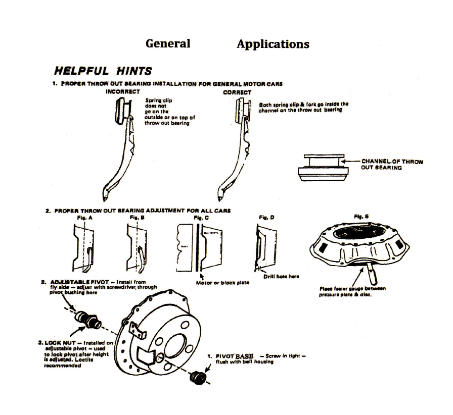
If your bell housing is a full 360 degree bell housing, first determine whether or not your T.O. Bearing is of sufficient length and is at the proper pivot angle. Disconnect the adjustment rod so that the fork is free. Move the fork by hand toward the transmission until the T.O. bearing contacts the clutch pressure plate fingers. At this point, check the angle of the fork as it comes out of the bell housing. It should be coming out straight or be slightly angled toward the engine. See Fig. A. If the angle is toward the transmission, See Fig B, you are past the Center Line with the bearing and are losing all mechanical leverage. To correct this problem, install a slightly longer T.O. bearing (with flat face)) or use an adjustable ball stud. Be sure to use the McLeod Adjustable Length T. 0. Bearing #16505 or its equivalent
When using a scatter shield with a motor plate or block plate, See Fig. C, use of an adjustable ball stud or intermediate T.O. bearing is recommended. To ensure proper adjustment for release on most high performance or drag cars, a hole should be drilled into the bell housing under the clutch assembly large enough to permit entry of a feeler gauge, See Fig D.
When adjusting with a feeler gauge, push the pedal all the way to the floor (or pedal stop); then, by adjusting the clutch rod, slide the feeler gauge between the disc and pressure plate until you have .050" air gap, See Fig. E. When .050" is adjusted into the clutch let the pedal up. Your clutch assembly should be properly adjusted.
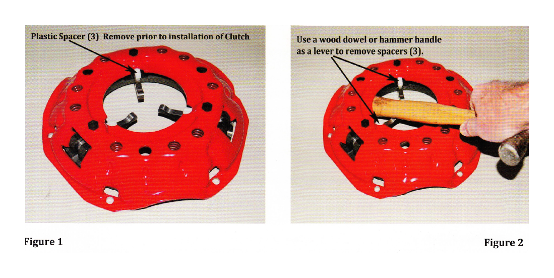
When installing a clutch with a Long or Borg & Beck style pressure plate assembly you must remove the plastic spacers between the fingers and the pressure plate cover before you install the clutch. This is a simple process to perform. Using a wood dowel or the handle of a hammer you can lever the finger pressure from the finger to the cover. See photo 1 & 2. Place the wood hammer handle under the cover and over the finger and press down on the head of the hammer to release the tension holding the plastic spacer in place. Remove the spacers (3) one at a time. Do not let your finger go between the clutch lever and the cover during this procedure or you will get pinched, as there is strong spring pressure on the lever!
Ford Applications
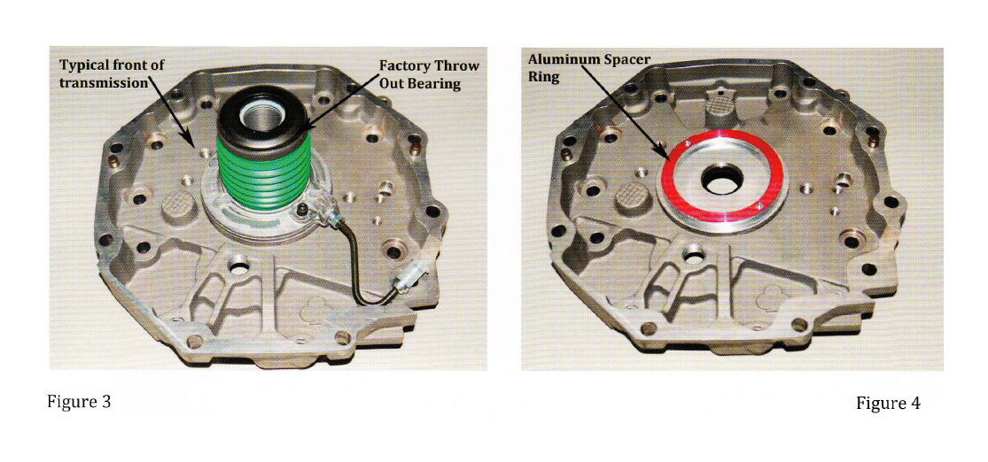
Some Ford installations require a spacer to be installed between the stock hydraulic throw out bearing and the front face of the transmission. Kits #75101, 75102, 75201 & 75202 require the installation of this spacer ring. This is an easy procedure to perform. Remove the screws retaining the throw out bearing from the front of the transmission. Place the spacer onto the front of the transmission and then re-install the throw out bearing. This spacer will position the throw out bearing at the correct height to contact the fingers of the pressure plate. See Figures 3 & 4.
Important Clutch Installation Hints
The following check list is a reminder of the necessary inspection points and precautions required insuring a trouble-free clutch installation.
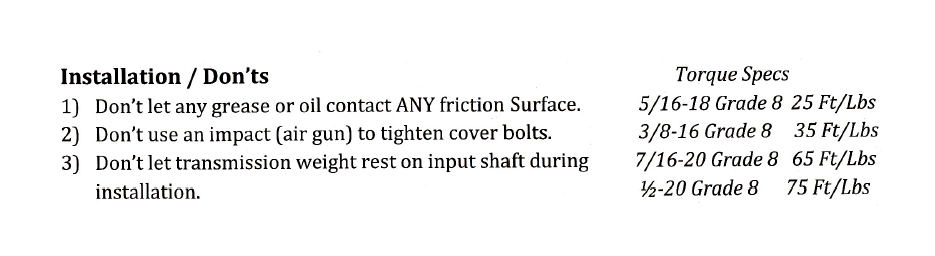
Installation / Do's
1) Determine cause of original clutch failure. Cause of first clutch failure (if not wear) MUST be found and corrected. If oil is present on clutch plate, cause of leak MUST be corrected before installation of new clutch unit.
2) Check splines on transmission input shaft for signs of abnormal wear or twisting. Slide new disc on spline by hand gently to check fit. Disc should move FREELY on splines.
3) Remove ALL oil or grease from friction surfaces on flywheel and cover assembly. Surfaces MUST be clean and dry. Also clean input shaft spline with a wire brush. Lubricate with dry graphite spray if needed.
4) To insure proper operation, friction surface of flywheel MUST be resurfaced. Check dowel pins, they must be smooth and straight.
5) If throw-out bearing is worn, replace it, better now than later.
6) Closely inspect pilot bearing or bushing for excessive wear to avoid transmission shaft misalignment. Replace it if any doubts.
7) Use clutch alignment tool to insure disc and cover are properly aligned with pilot bearing.
8) If using an aftermarket scatter shield/bell housing, checking center hole run-out is highly recommended.
9) Be sure all special type bolts, if any, are replaced in their proper locations.
10) Torque all clutch cover bolts evenly, to factory recommended spec, using a progressive "criss-cross" tightening pattern.
11) Before completing installation, inspect all clutch linkage parts (fork, clevis, pins, etc.) for signs of wear and replace ALL worn pieces. Grease all pivot points in linkage system.
12) Adjust clutch pedal "free play" to correct specifications. Throw-out bearing should not be tight against clutch fingers. 1/8" - is recommended, except cable linkage.
Limited Warranty
McLeod Racing LLC, Products are warranted to be free from defects in material and workmanship for the period of ninety (90) days, from the date of purchase. McLeod does not warrant or make any representations concerning its products when not installed and used strictly in accordance with the manufacturer's instructions for such; installation and operation, and in accordance with good installation and maintenance practices of the automotive industry. McLeod will not be held liable for the labor charges and other intangible or consequent losses that might be claimed as a result of the failure of any part, nor shall it be liable for damages or injury to persons or property resulting from the misuse or improper installation of any part subject to this warranty.
No merchandise may be returned for any reason unless prior return merchandise authorization number (RMA) has been obtained from McLeod.
McLeod reserves the right to examine all parts returned for warranty claim to determine whether or not any such part has failed because of a defect in material or workmanship. McLeod obligation under this warranty shall be limited to repairing, replacing or crediting, at its option, any part found to be defective. All products returned to McLeod for warranty inspection must be prepaid by the customer under this warranty. There are no other warranties, either expressed or implied, which extend beyond those set forth in the preceding paragraph. 10002
