FREE 1 to 3-Day Delivery on Orders $119+ Details
Best Sellers


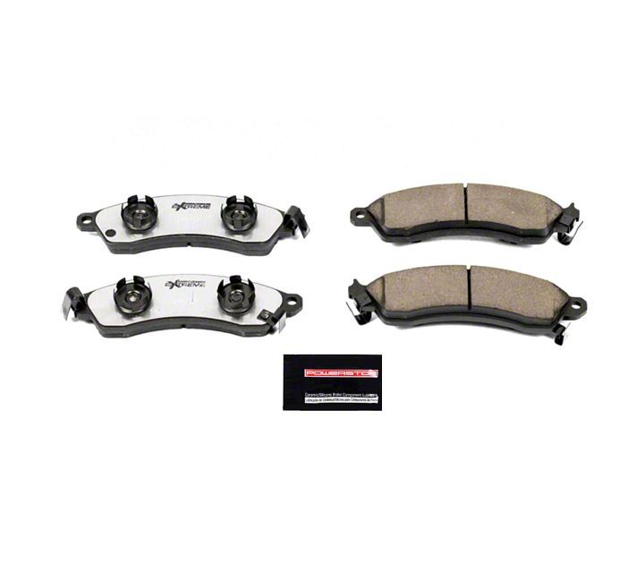
Power Stop Z26 Extreme Performance Ceramic Brake Pads - Front Pair on 1994-2004 Bullitt, Mach 1, Cob
Shop Parts in this Guide
Front Brake Pad Installation Guide
The installation guide is for reference only. Please refer to the vehicle’s service manual or professional installer for complete instructions.
Ninety percent of the brake pad changes you make during the life of your vehicle will be to the front brakes because they do 60% to 70% of the braking. On most cars, you can look through the openings on the outside of the wheel/rim assembly to see the pads. On some vehicles, you may have to remove the wheel to see the pads. Look at it from above or the side. The pad will be pressed against the shiny metal rotor. The best way to inspect a pad is through visual inspection. If the pad depth is less than 3/16 inch, plan on replacing it soon. If it’s less than 1/8 inch, you should change the brakes immediately.
You can also tell if the brakes should be replaced if you hear noise from the wear sensor on the pad. However, some parts do not have wear sensor clips, i.e. noisemaking clips that are mounted on the brake pad to tell you when the pads need to be changed. If you hear a screeching sound when you apply the brakes, then you are due for a brake change. (If the sound is more like a metal rasp or grinding sound, then you’ve already damaged your rotors and need to fix the brakes immediately.)
STEP ONE:
Have the following parts available before you start the brake change: 1) Power Stop brake pads such as the Evolution ceramic pads, 2) Power Stop cross-drilled or slotted rotors, 3) a bottle of DOT 3 or 4 brake fluid as recommended by your owner’s manual, 4) brake pad grease 5) a c-clamp. You should also have a car jack and jack stands.
STEP TWO:
Block the rear wheels so the car won’t roll once you jack it up. Put the car in park and set the parking brake firmly.
STEP THREE:
Before jacking the car up off the ground, loosen the lug nuts on the wheels just enough to break them free. Work them off just enough until they loosen their resistance and become easy to turn with the tire iron. Raise the car and support with safe jack stands under flat spots on the frame. Usually the frame support area is immediately to the rear of the front wheels.
CAUTION:
Always use jack stands. Never attempt to work on an elevated vehicle held in place only by a hydraulic jack.
STEP FOUR:
Remove the lug nuts and the wheel. It is best to work on one wheel at a time, leaving the other side intact as a point of reference. As a safety precaution, roll the wheel/tire assembly under the front-center of the car, between the jack stands, and set it down beneath the engine’s K-member. In the event of a faulty jack stand.
STEP FIVE:
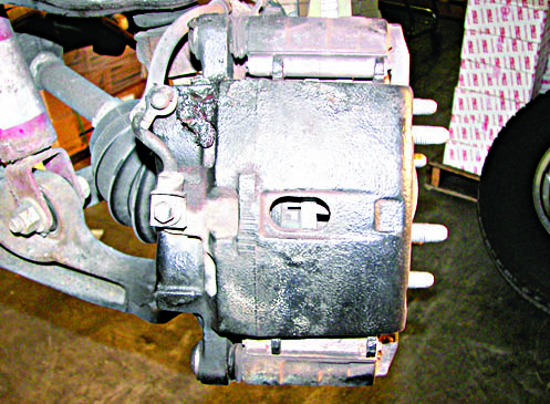
Review the brake components. A disc brake assembly is composed of a caliper, two brake pads, and a rotor. The caliper works on pressurized brake fluid through a piston in the caliper. The caliper has a fixed part bolted to the spindle knuckle and a slide part that holds the brake pads. The caliper is mounted with two bolts. These bolts usually have dust boots. When the brakes are applied, the caliper piston squeezes the pads against the rotor creating friction.
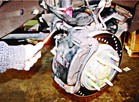
Fig. 1
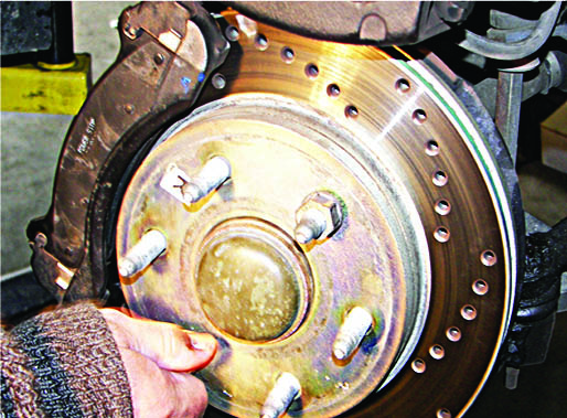
NOTE:
If you are not replacing or turning down the rotor, then install 2 lug nuts backwards to hold the rotor in place when removing the caliper (fig. 2).
Fig. 2
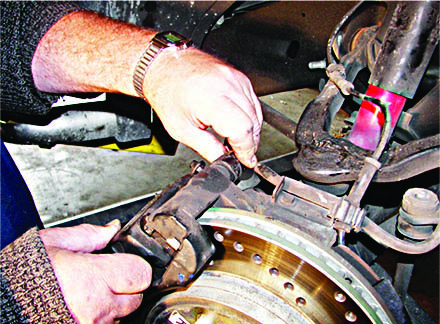
STEP SIX:
Remove the two bolts that hold the two parts of the caliper together (fig 3). Gently slide it out and away from the rotor. Hang the caliper inside the wheel well using a coat hanger, so that the hose is not stressed. Do not let the caliper dangle from the brake hose line. Inspect the inside of the caliper and remove the brake pads. Remove the two remaining bolts that hold the caliper slide to the knuckle. Use a wire brush to clean rust from the rails where the pad contacts the caliper.
STEP SEVEN:
With the caliper out of the way, remove the rotor. Sometimes the rotor rust will make it bind and you will need to use a mallet to loosen it. Tap both the front and back side alternating left and right, top and bottom of the rotor. The rotor thickness should be measured and compared to the minimum discard thickness that is etched on the rotor. If the thickness is less than this minimum, then the rotor should be replaced.
Fig. 3
STEP EIGHT:
The next step is to move the piston back inside the caliper. The piston has extended as the pad material wears. With new thicker pads, you must return the piston back inside the caliper body to give the thicker pads room for installation. First crack open the bleeder screw on the caliper to allow brake fluid to be relieved. Place a container under the caliper to collect the fluid. Get a large C-clamp, place the used brake pad over the face of the piston to protect the surface from marring, and work it back that way. As you turn the handle on the clamp, it will increase pressure on the piston, until it becomes flush with the surrounding metal. Brake fluid will be released through the bleeder. Then loosen and remove the C-clamp. Close the bleeder screw for now. If you cannot open the bleeder screw, then push the C-clamp in slowly to prevent unsafe back pressure and damage to the ABS modulator, brake valving or master cylinder. It may be necessary to drain some fluid from the master cylinder reservoir.
Fig. 4