 FREE 1 to 3-Day Delivery on Orders $119+ Details
Best Sellers


How To Install QA1 Caster Camber Plates on your 1994-2004 Mustang
QA1
Technical Support Line: (952) 985-5675 Fax Line: (952) 985-5679
21730 Hanover Ave.
Lakeville, MN 55044
www.QA1.net
INSTALLATION INSTRUCTIONS
QA1 P/N CC104MU Camber Caster Plates
1994-2004 Mustang 5.0/4.6 CC104MU
READ ALL INSTRUCTIONS CAREFULLY AND THOROUGHLY PRIOR TO STARTING INSTALLATION. PRODUCTS THAT HAVE BEEN INSTALLED ARE NOT ELIGIBLE FOR RETURN. USE THE PROPER JACKING LOCATIONS. DEATH OR SERIOUS INJURY CAN RESULT IF INSTRUCTIONS ARE NOT CORRECTLY FOLLOWED. A GOOD CHASSIS MANUAL, AVAILABLE AT YOUR LOCAL PARTS STORE, MAY ALSO AID IN YOUR INSTALLATION.
DISCLAIMER / WARRANTY
QA1 WARRANTS THAT THE PRODUCTS WILL BE FREE FROM DEFECTS IN MATERIAL AND WORKMANSHIP FOR ONE YEAR FROM DATE OF SALE TO THE ORIGINAL PURCHASER. QA1 MAKES NO OTHER WARRANTY OF ANY KIND, EXPRESS OR IMPLIED. QA1 SHALL HAVE NO OBLIGATION UNDER THE FOREGOING WARRANTY WHERE THE DEFECT IS THE RESULT OF IMPROPER OR ABNORMAL USE, YOUR NEGLIGENCE, VEHICLE ACCIDENT, IMPROPER OR INCORRECT INSTALLATION OR MAINTENANCE, NOR WHEN THE PRODUCT HAS BEEN REPAIRED OR ALTERED IN ANY WAY. QA1’S LIABILITY IN THE CASE OF DEFECTIVE PRODUCTS SUBJECT TO THE FOREGOING WARRANTY SHALL BE LIMITED TO THE REPAIR OR REPLACEMENT, AT QA1’S OPTION, OF THE DEFECTIVE PRODUCTS.
THE USER UNDERSTANDS AND RECOGNIZES THAT RACING PARTS, SPECIALIZED STREET ROD EQUIPMENT, AND ALL PARTS AND SERVICES SOLD BY QA1 ARE EXPOSED TO MANY AND VARIED CONDITIONS DUE TO THE MANNER IN WHICH THEY ARE INSTALLED AND USED. QA1 SHALL BEAR NO LIABILITY FOR ANY LOSS, DAMAGE OR INJURY, EITHER TO A PERSON OR TO PROPERTY, RESULTING FROM THE INSTALLATION, DIRECT OR INDIRECT USE OF ANY QA1 PRODUCTS OR INABILITY BY THE BUYER TO DETERMINE PROPER USE OR APPLICATION OF QA1 PRODUCTS. WITH THE EXCEPTION OF THE LIMITED LIABILITY WARRANTY SET FORTH ABOVE, QA1 SHALL NOT BE LIABLE FOR ANY CLAIMS, DEMANDS, INJURIES, DAMAGES, ACTIONS, OR CAUSES OF ACTION WHATSOEVER TO BUYER ARISING OUT OF OR CONNECTED WITH THE USE OF ANY QA1 PRODUCTS. MOTORSPORTS ARE DANGEROUS; AS SUCH, NO WARRANTY OR REPRESENTATION IS MADE AS TO THE PRODUCT’S ABILITY TO PROTECT THE USER FROM INJURY OR DEATH. THE USER ASSUMES THAT RISK!
INSTALLATION INSTRUCTIONS
1. Jack up the front of the vehicle and place jack stands securely on the frame of the car.
2. Remove front wheels.
3. Place floor jack under the control arm and jack up until slightly loaded.
4. Remove the strut shaft top mounting nut.
5. Remove the three nuts that hold the factory upper strut mounting plate in place and remove it from the car.
6. Carefully lower the jack to bring the strut shaft down through the strut tower center hole, but do not completely unload the jack: the spring may become dislodged any fly out, causing injury and/or damage to the vehicle.
7. Remove all washers, collars, bushings, etc., from the strut shaft.
8. Collapse the strut shaft down into the strut body far enough to remove the factory bottom plate, and dust boot.
9. Remove the factory dust boot and discard. Leave the factory bump stop on the strut shaft.
10. Check Figure 1 to identify the driver’s side and passenger’s side bottom plates.
11. A fourth hole will need to be drilled for installation. Place the appropriate bottom plate upside down on top of the strut tower, with the bolts protruding downward through the slots. This serves as a template for the locating the hole for the fourth bolt.
12. Sliding the plate as far outboard as the factory alignment slots will allow, insert an appropriate sized punch or marking pen through the nut of the bottom plate and mark the hole’s center location onto the top of the strut tower. Next, slide the plate as far inboard as possible and again mark the holes center location onto the top of the strut tower.
13. Remove bottom plate. Mark a point exactly between the two marks you’ve just made. This middle mark is where you will drill for the fourth Stud.
14. Center-punch, drill a pilot hole, then drill a 3/8” hole through the strut tower top. De-bur the hole.
15. Install the bottom plate beneath the strut tower with bolts protruding upwards through the factory mounting slots (see Figure 1). Make sure the bottom plate bolts move freely in the adjusting slots of the strut tower. If not, file the slots until they do.
16. Pull the strut shaft up out of the strut body and carefully jack up the control arm until the strut shaft is back in position, protruding through the large center hole.
17. Install a 5/16” thick washer over each bolt of the bottom plate. These washers will rest directly on top of the car’s strut tower (see Figure 1).
Figure 1
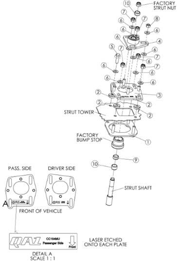
18. Refer to Figure 1 to identify the driver’s side and passenger’s side top plates.
19. Place the appropriate top plate over the bottom plate’s bolts. Install the washers and nuts on the two long bolts. The standard nut goes onto the short bolt.
20. With the three nuts still loose, slip another 5/16” thick washer between the strut tower top and the main plate. Insert the 3/8” x 1 1/4” bolt down through the flat washer, the main plate, the thick washer, the strut tower top, and thread it into the bottom plate’s nut.
21. Place a 3/8” washer over the 4 top plate bolts.
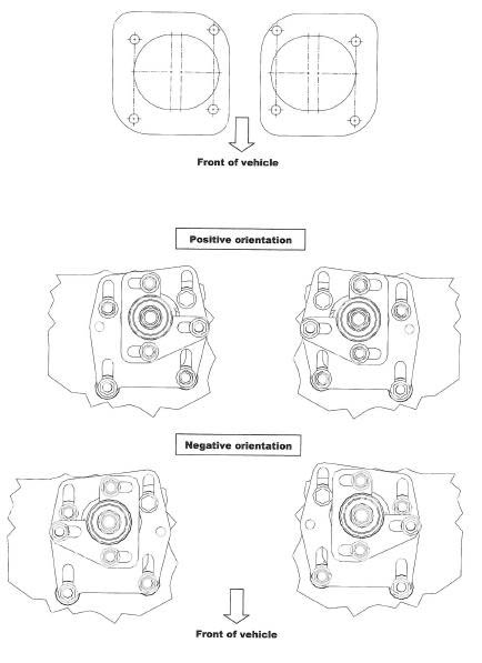
22. The orientation of the bearing housing assembly can be changed from “positive” to “negative” (See Figure 2). The majority of the cars will have the bearing plate in the “positive” orientation. Depending on the ride height (stock or lowered), the “positive orientation of the bearing housing assembly will allow camber settings varying from positive to over one degree negative.
23. Using Figure 2 as a guide, determine whether to install the bearing housing assembly’s in the “positive” or “negative” position. To change the orientation of the bearing housing assembly’s between positive and negative, you can swap the bearing housing assembly to the opposite sides of the car.
Figure 2
24. Install the appropriate bearing housing assembly on top of the washers, followed by three more washers and the 3/8” nylon locking nuts.
25. The strut shaft is installed through the spherical bearing with three of the 16mm I.D. spacers. The various strut manufacturers each have their unique length for the top threaded portion of the strut shaft. The user must determine the proper combination of spacers to put above and below the bearing for the struts being used. Spacers will be installed both above and below the bearing. Position the strut shaft just low enough that it will not hit the underside of the hood.
Suggestion: Before dismantling anything on the vehicle, lay a straight edge across the top of the fenders and measure down to the top of the strut shaft. Try to match that dimension when you install the strut with the spacers.
You can double check the clearance by carefully closing the hood with clay, putty, etc… The thickness will indicate how much hood clearance there is. Caster and camber settings change the strut shaft’s position relative to the hood. Double check final clearance with the car on the ground, final alignment completed, and while turning lock to lock. Clearance on the 1994-2004 Mustangs is extremely tight.
Note: When using a coil-over conversion kit, you will probably delete one of the spacers to allow room for the upper spring perch. You must be careful to ensure the upper spring perch will not touch the strut tower or the bottom plate during any combination of steering movement or suspension travel.
26. Reinstall the strut shaft top mounting nuts.
27. Temporarily tighten all the caster/camber plate adjusting nuts.
28. Pull the bump stop down slightly until after the alignment is completed. Then push it up until it contacts the bottom of the bearing plate.
29. Reinstall wheels and carefully lower the vehicle to the ground.
30. Remember to torque the lug nuts per Ford’s specs.
31. Have your car professionally aligned.
32. When the alignment, torque the caster/camber plate adjusting nuts:
Three camber nuts: 40 lb. ft.
Four caster nuts: 40 lb. ft.
Note: Because camber and caster can be adjusted independently, you can adjust one, lock it down, and then adjust the other. Always double-check all camber and caster measurements after any adjustment of even one parameter.
The camber adjustment slots when used in conjunction with the factory camber adjustment slots, allow the widest range of camber adjustment possible.
If you are adjusting towards the extreme limits of camber and/ or caster, be sure to double check the clearance between the strut shaft and the edge of the large center hole of the strut tower. Check not only with the wheels pointed straight ahead, but also while turning the steering wheel lock to lock. In some instances, Ford’s production tolerances on the positioning of that center hole can cause interference when camber or caster is adjusted towards the limit of travel.
REMEMBER THAT ANY TIME YOU MAKE ANY CHANGE IN CAMBER, CASTER OR RIDE HEIGHT, YOU MUST RE-ADJUST THE TOE SETTING.
Item # Part Number Material Description Quantity for one side
1 WELDMENT, BOTTOM PLATE 1
2 9033-303 SPACER, .38" ID X 1" OD X .276" 4
3 WELDMENT,TOP PLATE 1
4 BEARING HOUSING ASSEMBLY 1
6 9005-256 WASHER, FLAT 3/8" SAE 10
7 9014-253 NUT, NYLOCK 3/8-16 6
8 9014-333 NUT, HEX 3/8-16 1
9 9033-221 SLEEVE, .685" ID X .875" OD X .571" 1
10 9033-217 SLEEVE, .65" ID X .875" OD X .433" 2
To further upgrade your suspension, use other QA1 suspension products such as coil-overs, shocks, struts, springs, K-members, torque arms, panhard rods, sub-frame connectors, strut tower braces, rod ends, sway bars, tubular control arms, spherical bearings, carbon fiber driveshafts and more. For more information, please visit www.QA1.net.
