FREE 1 to 3-Day Delivery on Orders $119+ Details
Best Sellers


How to Install a Roush Cold Air Intake on your 2005-2009 Mustang GT
Installation Time
30 minutes
Tools Required
- 8mm deep well socket
- 10mm socket
- Ratcheting nut driver
- Extension for nut driver
- Ratchet for sockets
- Ratchet extension
- Flat blade screw driver
- T20 Torx bit
- MAF sensor screws (included)
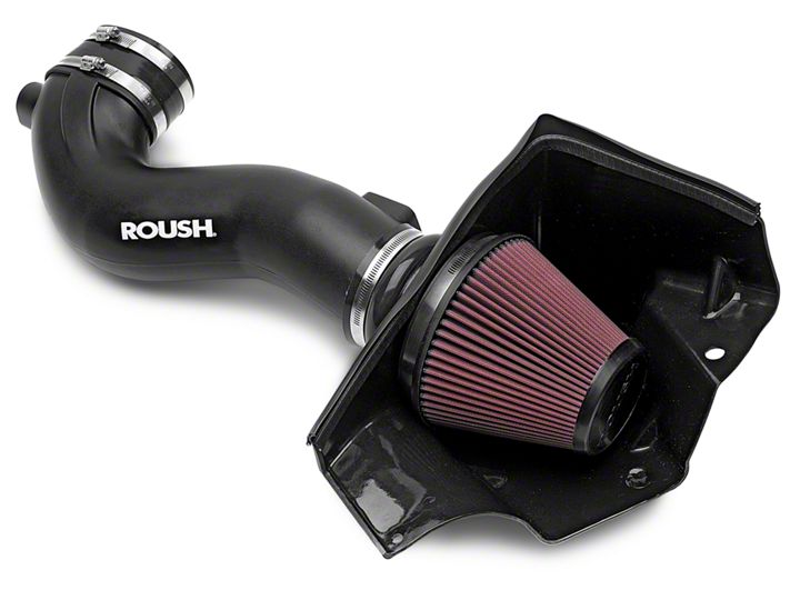
Shop Parts in this Guide
-Fig 1 shows the engine bay with factory air box, Mass Air Flow (MAF) tube and MAF sensor. Note: this car has the factory plenum intake cover with Running Pony Logo, fuel rail covers, throttle body cover and fuse box cover. –Fig 2 shows the parts included in the kit. Carefully unpack and inventory the parts for this kit.
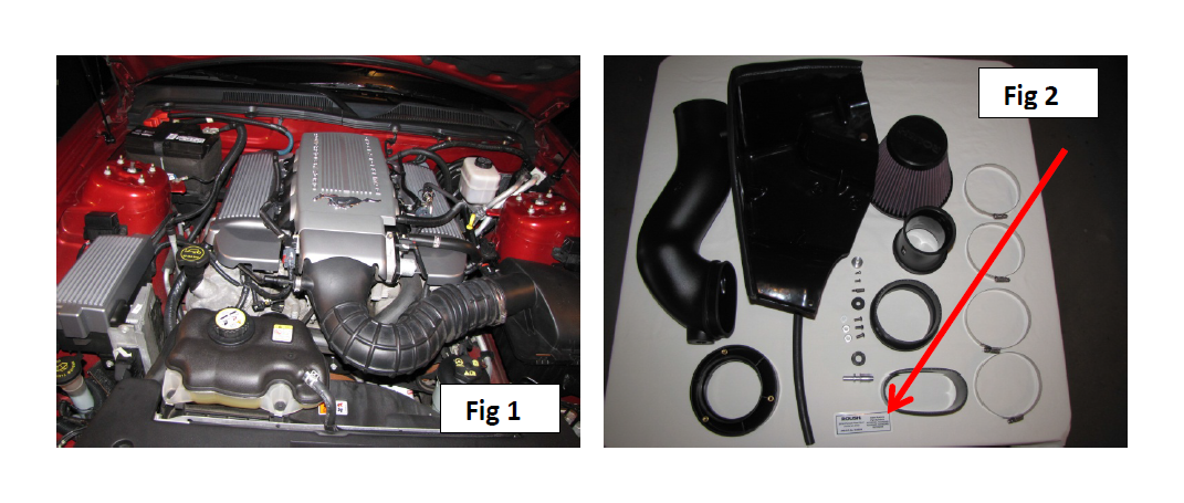
Note: This kit is street legal in most states provided the tube insert is used in the Roush intake tube. The insert serves as venturi/air restrictor and the kit will not require a re-tune with the tube insert installed. Removing the insert tube insert will void the California Air Resources Board (CARB) certification and will require a re-tune.
A CARB sticker (see red arrow in -Fig 2) is included in the kit and is required to be displayed to meet California smog tests. Mustang GT vehicles built between September 2004 through April 2005 (inclusive) and all 2007, 2008 and 2009 Mustang GT vehicles are not included in the CARB exemption because they use a hydrocarbon absorber. It will not be legal to operate these vehicles for “on-road” use in the state of California or any other CAA Sec.177 state.
If your vehicle has the plenum cover, throttle body extension cover and fuel rail covers installed, the plenum cover, extension cover and passenger side fuel rail cover must be temporarily removed to provide access to the factory breather tube connection on the cam cover.
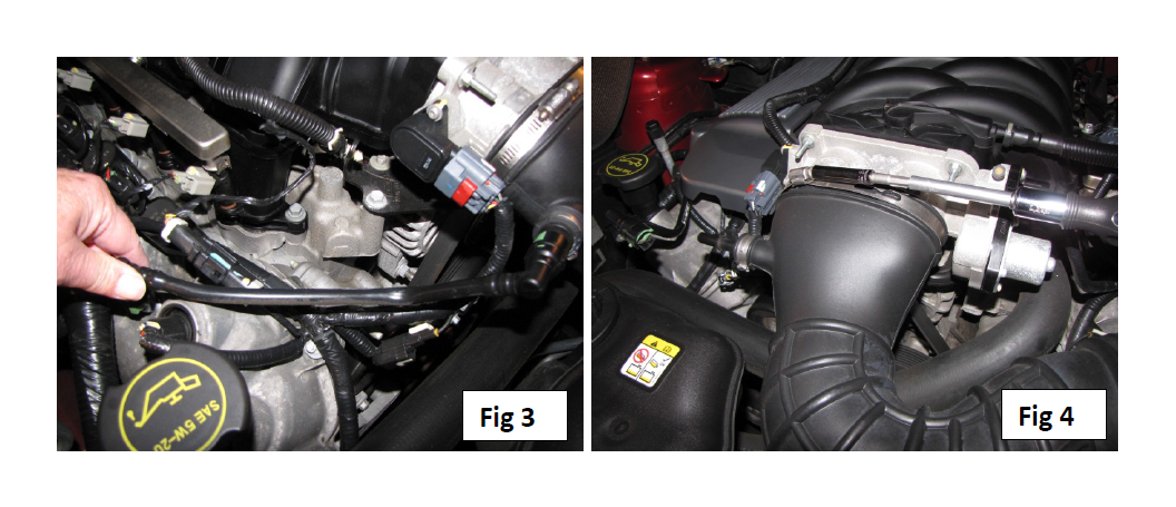
Begin installation of the CAI kit by removing several factory components. Remove the breather tube. Push the small ends of the green tabs on the connectors to disengage them from the nipples on the cam cover and MAF tube -Fig 3. Using an 8mm socket, loosen the band clamp on the MAF tube where it attaches to the throttle body –Fig 4.
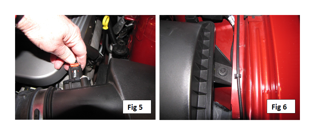
Disconnect the MAF sensor by pushing the red tab toward the firewall and pulling the connector and harness away from the factory MAF sensor –Fig 5. Use a 10mm socket to remove the bolt holding the air box on the fender –Fig 6 and then remove the entire air box and MAF tube assembly by lifting it up and away from the engine bay.
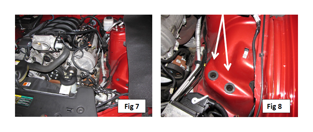
–Fig 7 shows the assembly removed. Make sure the two rubber grommets from the bottom of the airbox are retained/replaced on the fender –Fig 8.
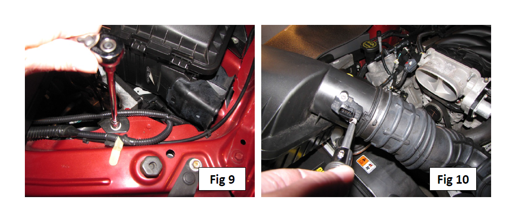
Use a 10mm socket to remove the bolt on the ABS bracket –Fig 9. Retain the bolt for later use. Use the #20 Torx bit to remove the MAF sensor from the factory MAF tube –Fig 10. Do not reuse the factory screws.
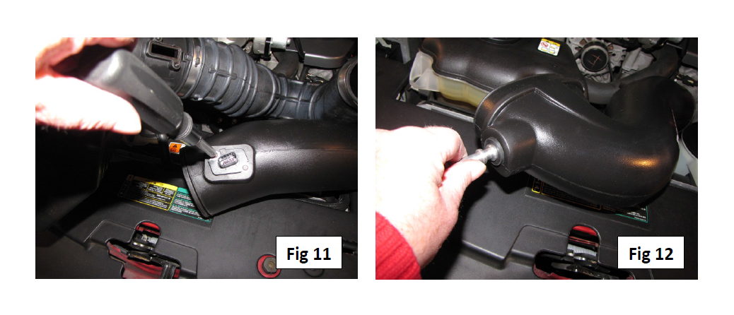
Line up the slots in the Roush MAF tube insert with the slot on the Roush intake tube and install the MAF sensor in the same direction as it was installed on the factory tube using the two #8-32x3/8” button head bolts supplied with the kit –Fig 11. Seat the rubber grommet in the intake and then insert the aluminum fitting into the grommet –Fig 12.
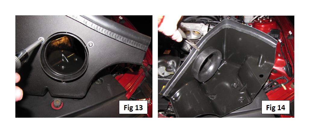
Assemble the cool air dam by inserting the filter adapter and lining up the three holes. Use the three ¼”-20x1/2” button head screws and three ¼” flat washers to attach the filter adapter as shown in –Fig 13. Attach the 22” weather strip to the air dam starting at one end of the dam. Use a needle nose pliers or similar tool to crimp the weather strip –Fig 14.
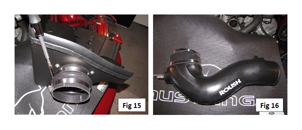
Attach the hump hose to the outside of the filter adapter using two #64 hose clamps. For appearance purposes, the hose clamp adjustment screws are positioned where they will be out of site in –Fig 15. Tighten the hose clamp on the filter adapter with an 8mm socket. Leave the other #64 clamp loose for now. Attach the oval coupler to the Roush intake tube using two #72 hose clamps as shown in –Fig 16. Tighten the clamp that is closest to the aluminum fitting. Leave the other clamp loose for now. Again, consider where the hose clamp adjustment screws will be positioned for appearances.
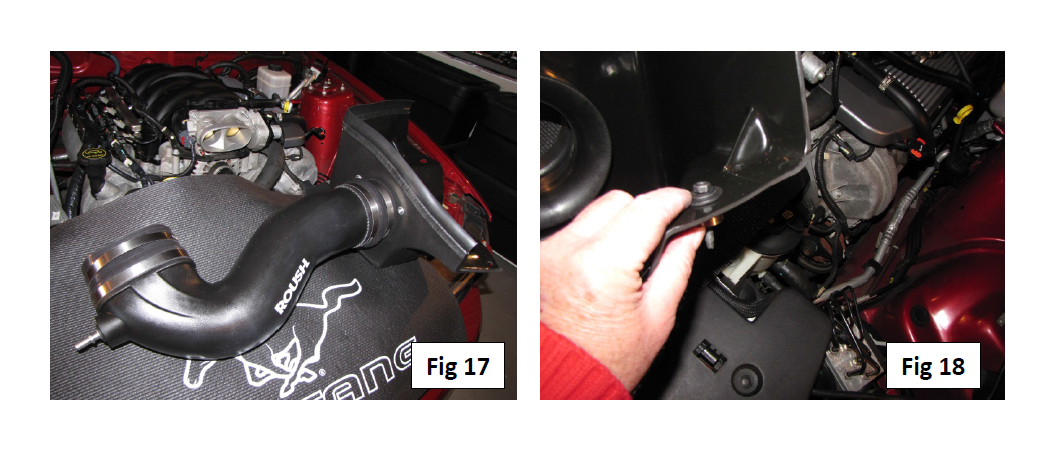
Insert the Roush intake tube into the hump hose. It takes some effort to push the tube into the hose as far as it will go (almost to the MAF sensor) as shown in –Fig 17. Tighten the remaining #64 hose clamp around the intake hose with an 8mm socket. Now take the Roush air dam assembly (with intake tube attached) and push the remaining end of the oval coupler onto the throttle body while simultaneously placing the air dam in the same space as the factory air box. Tighten the remaining #72 clamp on the oval connector/ throttle body with an 8mm socket. Insert the aluminum spacer through the bottom of the hole on the air dam with the fender bolt and ¼” fender washer through the spacer as shown in –Fig 18.
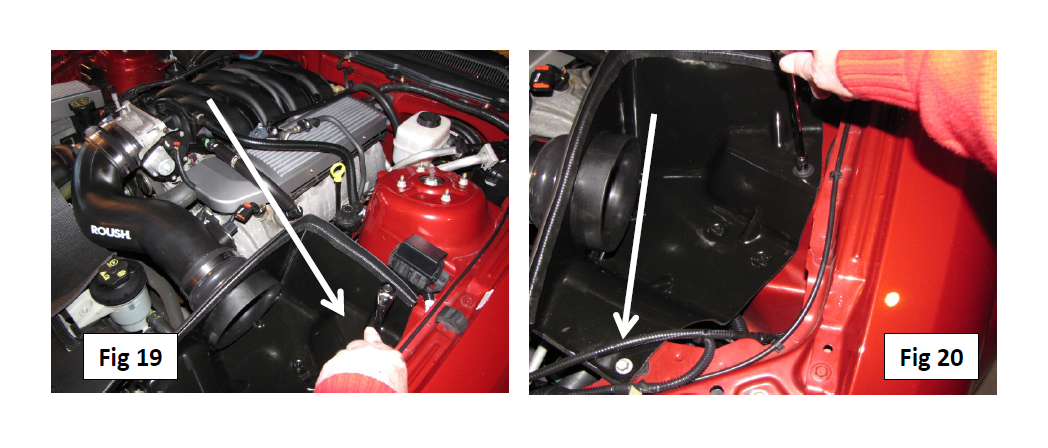
Using a 10mm socket, re-install the fender bolt –Fig 19 ensuring that nipples on the bottom of the air dam insert into the two rubber grommets on the fender. With the same 10mm socket, re-install the ABS bracket bolt –Fig 20 through the front of the air dam.
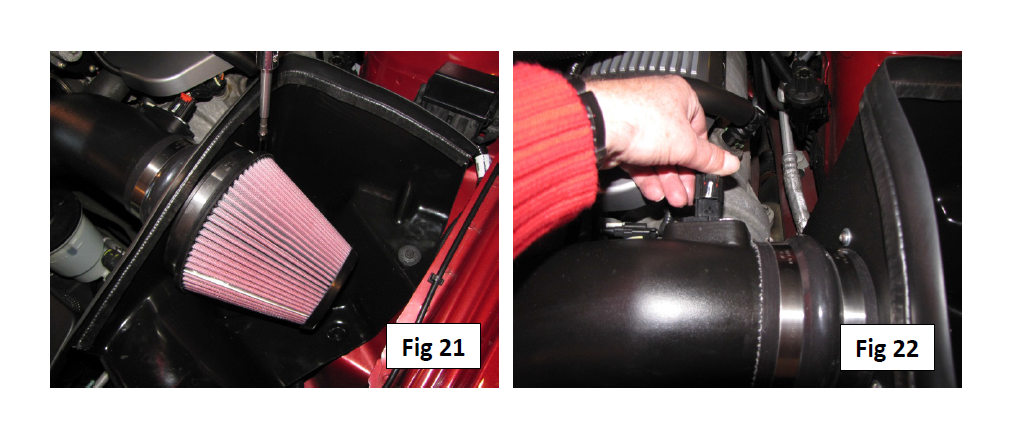
Install the premium filter by positioning it on the inside of the filter adapter. Tighten the supplied hose clamp with an 8mm socket –Fig 21. Again, consider where the clamp adjustment screw will be for aesthetic purposes. Plug the MAF sensor harness into the sensor previously installed in the intake tube –Fig 22.
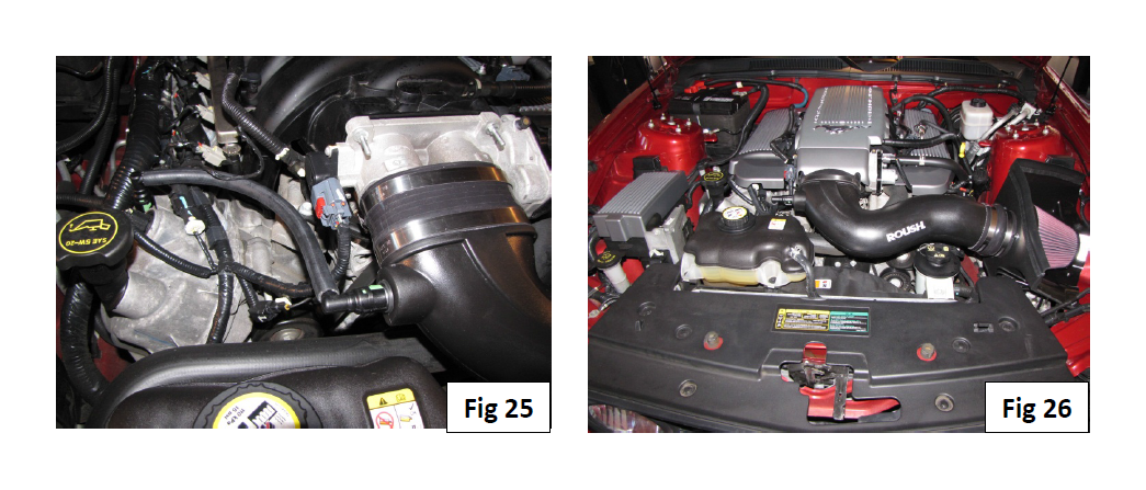
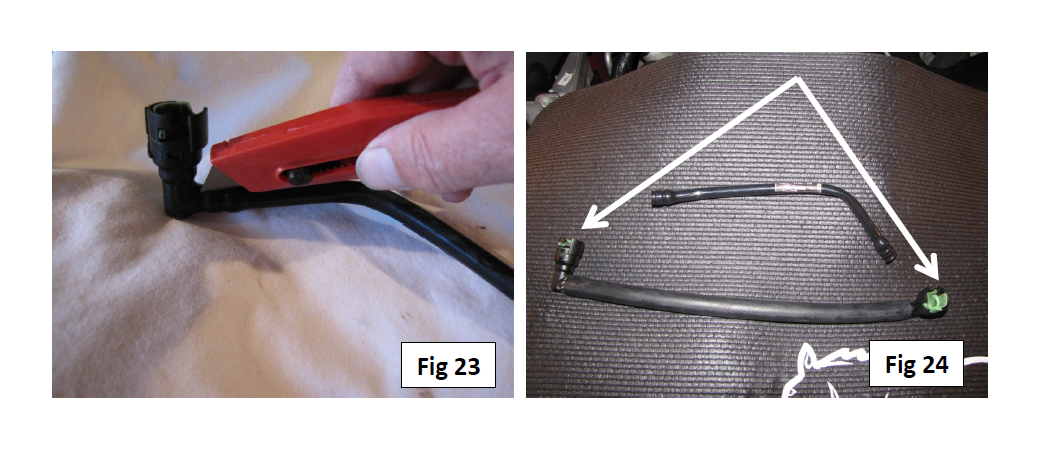
Take the breather tube and carefully cut the plastic “shrink wrap” that holds the connectors to each end of the factory breather tube –Fig 23. Insert the breather tube ends to the 3/8”x12” hose from the Roush kit as depicted in –Fig 24.
Attach the breather hose to the nipples on the cam cover and the aluminum fitting on the intake tube –Fig 25. This completes the Roush Cold Air Intake installation. Re-check the tightness of all fittings, screws, clamps and bolts. Re-install the plenum cover, throttle body cover and passenger side fuel rail cover if they were previously part of the vehicle. California residents should remember to apply the CARB sticker on the engine bay in plain sight. The completed installation is depicted in –Fig 26.