 FREE 1 to 3-Day Delivery on Orders $119+ Details
Best Sellers


How to Install Roush 2015+ Mustang 5.0L-V8 Power Pack Level 1 on your Mustang
Installation Time
1 hours
Tools Required
- 10 mm Socket
- Pliers
- Flat-head Screwdriver
- Trim Tool
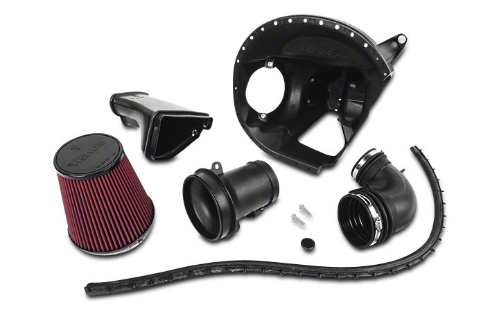
Shop Parts in this Guide
SECTION A – REMOVAL
The following section will guide you through the removal of the stock components. Special care should be taken to label fasteners and parts that are taken off during this procedure since many will be reused.
1. Cover both fenders with fender covers to protect the vehicle finish.
2. Disconnect the battery ground cable.
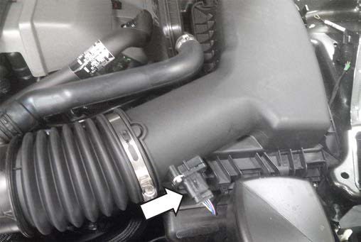
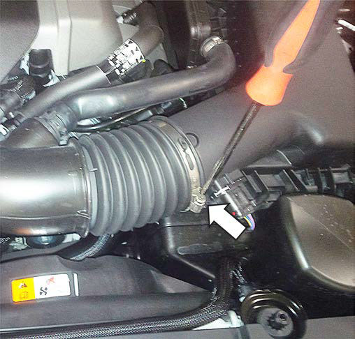
3. Disconnect the MAF sensor connector.
4. Loosen the clamp at the air box from the intake tube.
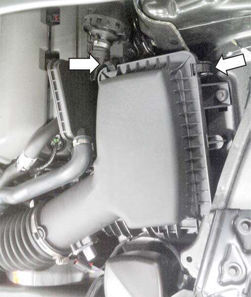
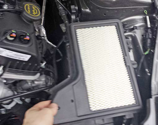
5. Release the two (2) latches holding the box lid to the lower box.
6. Remove the air box lid and filter. Retain the lid for use during installation.
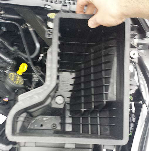
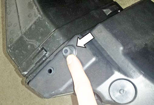
7. Using the 10 mm socket, remove the bolt holding the air box to the inner fender. Retain the bolt as it will be used during installation.
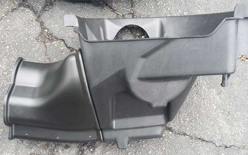
8. Remove the air box tray and dirty air inlet from the vehicle.
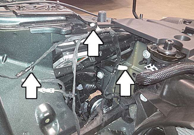
9. Remove the three (3) clips shown on the inner fender to give the slack needed in the wiring harness.
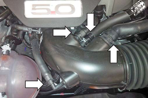
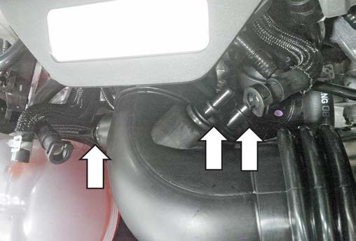
10. Remove the hose clamp and three (3) quick connect fittings from the clean air tube.
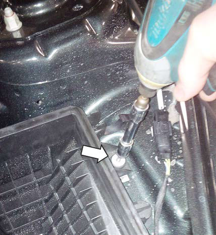
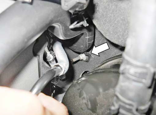
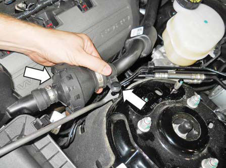
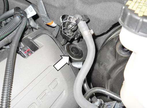
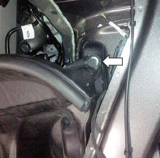
11. Using a 10 mm wrench or deep-well socket, remove the nut retaining the induction resonance tube to the firewall behind the driver side cylinder head.
12. Using a trim tool, pry up on the push pin retaining the induction resonance tube and remove the tube from the vehicle.
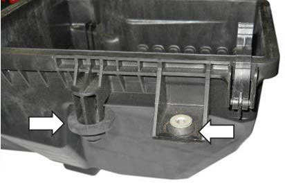
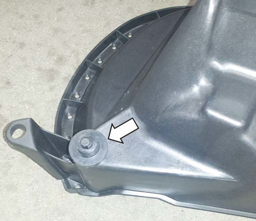
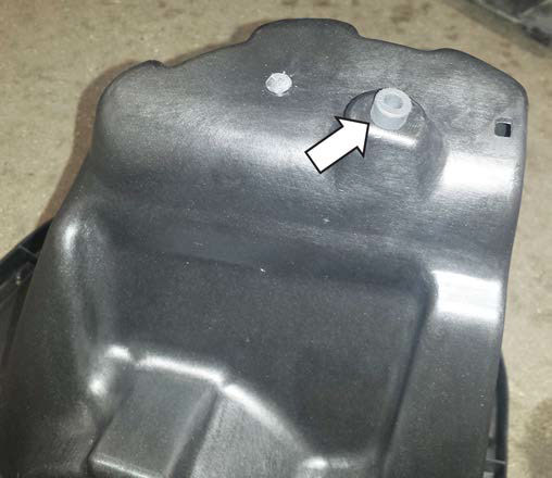
13. Remove the steel bushing followed by the two (2) rubber grommet from the stock air box tray. Retain these for use during installation.
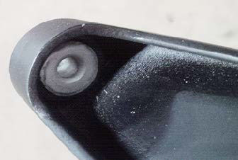
14. Remove the rubber isolator from the bottom of the stock air box tray and retain for use during installation.
SECTION B – INSTALLATION
1. Install the resonance tube delete grommet (P/N: W651016) into the firewall.
2. Install the grommet and sleeve that was removed from the stock air box into the ROUSH air box (P/N: 131550-9A612). TIP: Install the rubber grommet first, then install the steel bushing.
3. Install the second grommet onto the air box (P/N: 131550-9A612).
4. Install the rubber isolator into the bottom of the air box (P/N: 131550-9A612).
5. Insert the dirty air inlet (P/N: 1315-9F763-A) into the air box (P/N: 131550-9A612).
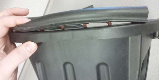
6. Place the bulb seal (P/N: 131550-9C664) onto the top of the air box (P/N: 131550-9A612) and clip into the holes. Trim ends as required.
7. Insert the air box assembly into the vehicle.
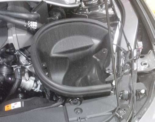
8. Using a 10 mm socket and the bolt removed from the stock air box, attach the air box to the vehicle. Torque to 8 Nm.
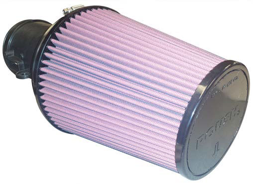
9. Loosely attach the air filter (P/N: 131550-9601R) to the filter tube, leave the clamp loose so you can hide it once installed on the vehicle. Make sure the arrow on the filter is 90 degrees to the MAF sensor boss as shown.
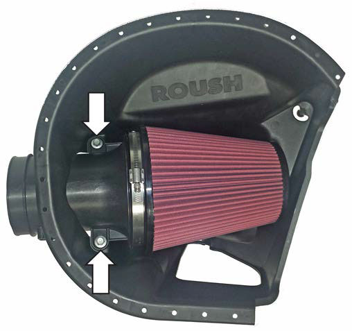
10. Slide the filter tube assembly into the air box (P/N: 131550-9A612), making sure the sensor boss is pointed toward the front of the vehicle. Using a 10 mm socket, install the two (2) bolts (P/N: W500224). Torque to 10 Nm. Rotate the air filter clamp to a suitable location and torque to 3 Nm.
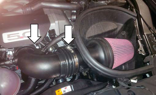
11. Install the clean air tube assembly (P/N: 131550- 9R504) onto the throttle body first and then the filter tube. Tighten the clamps to 3 Nm.
12. Reconnect the three (3) hoses with quick connect fittings to the mating push-on barbs.
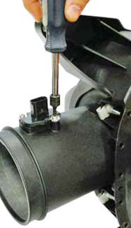
13. Remove the MAF sensor from the factory air box by removing the two (2) T-15 torx screws.
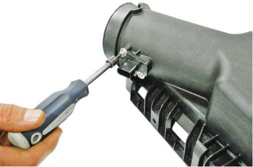
14. Re-install the MAF sensor into the ROUSH filter tube (P/N: 131550-12B579). Reattach the connector. Torque screws to 2 Nm.
PCM FLASHING
Proceed with steps 1-2 if you have a SAE J2534 pass through device (e.g. Puma, VCM I, VCM II)
If you do not have a SAE J2534 device visit your local ROUSH Dealer or Performance Shop with the appropriate tools for PCM Calibration
1. If equipped with a SAE J2534 pass through device, refer to the RDT-CALIM manual found on our website, rdt.roush.com The RDT-CALIM manual will guide you through the ROUSH Diagnostic Tool (RDT) software installation process and the ROUSH PCM flashing procedure detailed in RDT-CALIM.
2. Once the PCM has been successfully recalibrated, start the engine and check for unusual noises, dash service lights, and unusual operation. If problems are detected, immediately stop the engine or vehicle, diagnose and repair the problem.
