 FREE 1 to 3-Day Delivery on Orders $119+ Details
Best Sellers


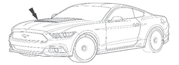
How to Install Roush Hood Scoop - Unpainted on your Mustang
Installation Time
1 days
Tools Required
- Isopropyl Alcohol Packets or 50/50 Alcohol/Water Solution
- Drop Cloth
- Scissors
- Masking Tape
- Deburr Tool
- Drill
- Drill Bits: 1/8", 5/16", 7/16", 1.0" Hole Saw
- Corrosion Inhibitor (Motorcraft PMP-19500-6000 Clear Topcoat recommended)
- 1/4” Drive Ratchet
- 1/4" Extension
- 1/4" 10 mm Socket
- 1/4" Torque Wrench
- Round File
- Rubber Roller
- 13 mm Wrench
- 8 mm Socket
- Center Punch
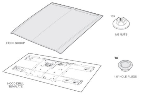
PACKING LIST FOR 2015 MUSTANG HOOD SCOOP
WORK SAFELY! Perform this installation on a good clean level surface for maximum safety with the engine turned off.
PAINTED PART PREPARATION
STOP Unpainted/primed parts purchased from ROUSH require further preparation prior to being painted. Removal of any excess plastic fl ashing and sanding of the primed parts is required prior to paint application. The primed parts as received should not be painted without further surface preparation.
HOOD SCOOP GRAPHIC PREPARATION (OPTIONAL)
1. Place the hood scoop on a suitable working area.
2. With the scoop facing away from you and the painted surface facing upward, remove the backing from the adhesive side of the rear hood scoop graphic.
3. Position the rear LH graphic in the LH feature of the scoop. Once the graphic is in position, wipe from the center out towards each side to set the graphic into position using a fl at-blade tool (credit card). Remove the top carrier from the graphic.
4. Repeat for the rear RH graphic.
5. Rotate the hood scoop upside down, with the front facing you. Use care to not scratch or mar the painted surface.
6. Remove the backing from the adhesive side of the front inlet graphic. Position the front inlet graphic along the edge of the front of the scoop. Wiping from the center out towards each side, set the graphic into position using a fl at-blade tool (credit card). Remove the top carrier from the graphic.
HOOD SCOOP INSTALLATION
1. Make sure the vehicle’s sheet metal is clean and dry. The sheet metal should be between 61°-81°F (16°-31°C).
2. Open the hood and remove the inner hood liner by removing the push pins with a proper trim tool. Use caution to not lose the push pin retainers while removing them.
3. Place a large drop cloth in the engine bay underneath the hood. Cover any area directly under the area where the hood is to be drilled.
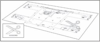
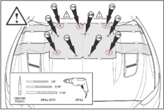
4. Carefully cut out the hood outer drill template. Take extra care in the areas indicated with black arrows. These areas are crucial to the correct alignment of the template.
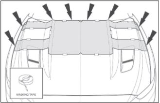
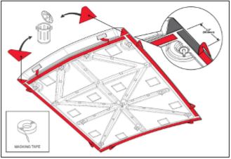
5. Install the hood scoop drill template. With the hood closed, align the template to the hood outer sheet metal as shown. Secure the template to the hood with masking tape.
Attention: Confi rm the template is properly centered and aligned before continuing to the next step.
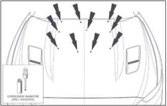
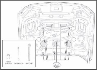
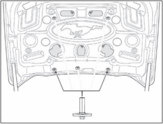
6. Center punch the outer sheet metal of the hood at each of the ten (10) locations indicated on the template. Drill each center punched location with a 1/8" drill bit. Be sure to move the washer nozzles aside when drilling the rear outer corners. At the three (3) rear locations and the two (2) outer front locations, drill straight through both the outer and inner sheet metal. Refer to the circled areas in the illustration below.
CAUTION
Care should be taken in order not to damage any of the vehicle components underneath the hood. Pay close attention to the two (2) rear most outer holes closest to the windshield as the washer jet nozzles are located underneath this area.
Enlarge each hole on the outer sheet metal only to the size indicated on the template. Note that the center hole should be enlarged to 5/16” while the other nine (9) holes should be enlarged to 7/16”.
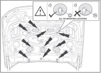
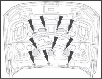
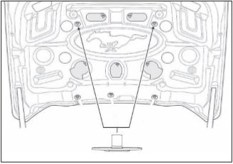
7. Open the hood and locate the fi ve (5) 1/8" holes drilled into the inner sheet metal during Step 6. Enlarge each of the fi ve (5) 1/8" hole locations with a 1.0" hole saw.
CAUTION
Care should be taken not to damage the hood outer sheet metal while drilling the fi ve (5) 1.0" access holes. Pay close attention to the two (2) rear most outer holes closest to the windshield as the washer jet nozzles are located underneath this area.
Deburr and apply corrosion inhibitor to each of the fi ve (5) 1.0” access holes. Allow to dry.

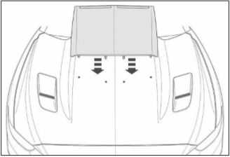
8. With the hood closed, test fi t the hood scoop on the hood. Align the ten (10) studs on the hood scoop through the holes drilled in the hood. Secure the hood scoop to the hood with masking tape.
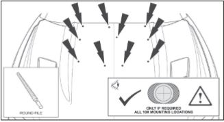
9. Open the hood and inspect each of the ten (10) mounting locations. Confi rm the alignment of the hood scoop fasteners with the holes drilled in the outer sheet metal.
10. If the fasteners and holes are not aligned, remove the hood scoop and use a round fi le to adjust the holes in the sheet metal accordingly.
11. Deburr and apply corrosion inhibitor to all of the holes drilled in the outer sheet metal. Allow to dry.
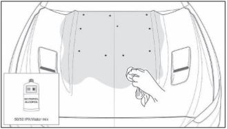
12. Use a 50/50 (alcohol/water) solution to clean the area of the hood where the hood scoop will be installed.
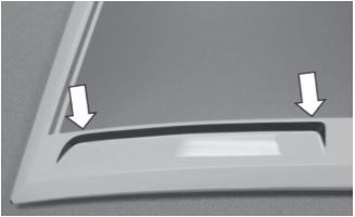
13. Prepare the hood scoop for installation. Peel 2.0" (50.8 mm) of each tape liner and secure it to the top of the hood scoop. Remove the liners from the LH and RH triangular die cuts.
14. Install the hood scoop through the holes and onto the hood sheet metal. Do not allow the exposed double-sided tape to adhere to the sheet metal until you have confi rmed the hood scoop is aligned, then push down.
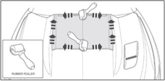
15. Remove all of the tape liners in the directions indicated below.
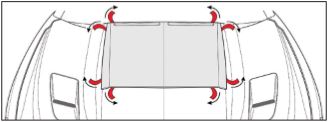
16. Using a rubber roller or the palm of your hand, apply 15 ft-lb of force to the tape area in order ‘wet out’ the double-sided tape.
17. Secure the hood scoop to the hood sheet metal. Open the hood and install ten (10) M6 nuts. Hand tighten only, do not use power or pneumatic tools.
18. Torque all fasteners to 3.5 Nm.
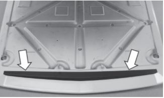
19. Install one (1) rubber hole plug into the access hole shown below that was drilled in Step 7.

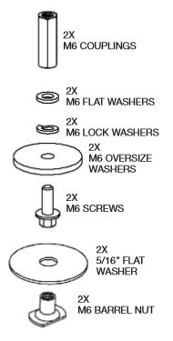
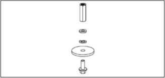
20. Place one (1) large fl at washer (P/N: 92140A114) onto (1) M6 screw (P/N: W500013) followed by one (1) M6 lock washer (P/N: 91202A234) then one (1) smaller M6 fl at washer (P/N: 91455A120) and fi nally one (1) M6 hex coupling nut (P/N: 93355A954) and torque the assembly to 10 Nm. Repeat this process with the remaining hardware to create one (1) more coupling assembly.
21. Thread one (1) coupling assembly onto each of the studs as shown below. Torque to 3.5 Nm. NOTE: THE WINDSHIELD SPRAY NOZZLE TUBES ARE LOCATED NEAR THE STUDS
22. Thread one (1) M6 Barrel Nut (P/N: 90594A350) with one (1) 5/16" Oversize Flat Washer (P/N: 91090A119) onto each of the studs as shown below. Torque to 3.5 Nm.
23. Reinstall the hood inner liner using the previously removed push pins.
24. Carefully remove drop cloth, making sure not to spill any of the metal shavings into the engine bay. Vacuum up any stray metal shavings.
Congratulations!!! The installation is complete.
