 FREE 1 to 3-Day Delivery on Orders $119+ Details
Best Sellers


How to Install Scott Drake Adjustable Rear Lower Control Arms on Your 2005-2014 Mustang
Installation Time
2 hours
Tools Required
- 18mm Socket
- ½” Drive Ratchet Wrench
- Torque Wrench
- Flat Head Screwdriver
- Analog Protractor or Digital Angle Finder
- Two 1 1/8” Wrenches for Jam Nuts
- Grease Gun with synthetic grease (UHMW Bushed Arms only)
- Safety Glasses
- Gloves
- Jackstands (If you are not using a lift)
Race Rod Ends - 5R3Z-5A649-BRRE
TOOLS NEEDED FOR INSTALLATION
• 18mm Socket
• ½” Drive Ratchet Wrench
• Torque Wrench
• Flat Head Screwdriver
• Analog Protractor or Digital Angle Finder
• Two 1 1/8” Wrenches for Jam Nuts
• Grease Gun with synthetic grease (UHMW Bushed
Arms only)
• Safety Glasses
• Gloves
• Jackstands (If you are not using a lift)
Thank you for your purchase of the Drake Muscle Cars Rear Lower Control Arms!
- WARNING! -
Always wear gloves and protective eye-wear when working around
automotive equipment.
- WARNING! -
Always support a raised vehicle with jack stands.
- WARNING! -
Please review these instructions carefully. If any part of this procedure seems out of your scope of capabilities, please seek a certifi ed mechanic to perform this installation. Failure to reassemble the suspension properly can
lead to serious injury.
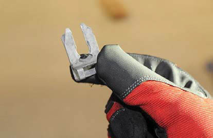
Figure 1
INSTALLATION
Make sure the emergency brake is disengaged and raise the vehicle. Make sure to use jack stands if you are not using a lift. Support the weight of the rear of the vehicle on the rear axle with jack stands or pole jacks if using a lift. One on each side of the axle tube.
Using a flat head screwdriver disconnect the clip retaining the emergency brake cable to the caliper on both sides. Lift up on the cable and dislodge from caliper. (See figures 1 & 2)
Remove the driver’s side lower control arm front bolt and nut using an 18mm socket.
(See figure 3)
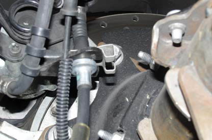
Figure 2
Remove the driver’s side lower control arm rear bolt and nut using an 18mm socket.
Repeat previous two steps to remove the passenger side lower control arm.
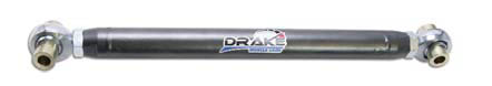
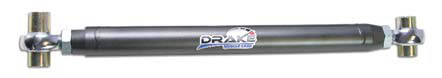
Install Drake Muscle Cars Lower Control Arms:
As a starting point adjust the length of the Drake Muscle Cars Lower Control Arms to the length of the factory arms. To adjust, loosen the jam nuts and turn the bar to either lengthen or shorten. Then, retighten the jam nut. (See figure 4)

Figure 3
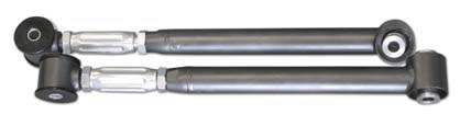
Install the control arms with the wider bushing end going to the rear of the vehicle, with the side offset furthest from the centerline of the control arm to the inside of the vehicle. This offset allows the control arms to be mounted straight within the mounts. (See figures 5a & 5b)
For control arms with UHMW bushings, Apply grease to the crush sleave and on the outside of the bushing flanges. Make sure the zerk fittings are facing down.
Using the factory hardware, tighten and torque all bolts to 175 N-m (129 ft-lbs)
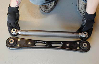
Figure 4
Reinstall the brake cables and retaining clips. Zip tie the brake cable to the adjustable tubular control arms or route the cable through the control arm on the billet control arms like the factory does.
Using a grease gun with a synthetic lube, lube each zerk fi tting with 1-2 pumps on control arms equiped with the UHMW bushings and grease zerks. The spherical bearings and rod ends are teflon/PTFE lined and therefore self lubricating.
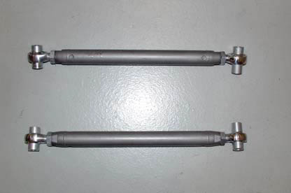
Figure 5a
Relocating the pinion angle via the adjustable control arms
Lowered vehicles will require the pinion angle to be reset for optimal performance. Most cars like the following settings: Automatics 1-2 degrees negative and Manuals 2-3 degrees negative. Negative means the differential is pointed down in relation to the driveshaft.
The rear of the car needs to be resting on its own weight and sitting as close to ride height as possible on a level surface. Ultimately this can be achieved either by using drive on ramps or lift that supports the vehcile on the tires. This can also be achieve with jack stands under the rear axle tubes and the front control arms
Use either an anolog protractor or digital angle finder (inclinometer) to measure the
angle of the rear portion of the two piece drive shaft.
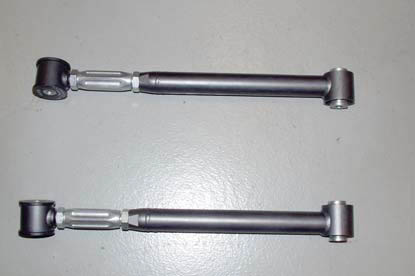
Figure 5b
Measure the angle of the differential pinion flange. (See figure 6)
Subtract the pinion flange angle from the front driveshaft angle to find the net pinion angle.
Loosen the jam nuts on the new control arms to lengthen or shorten the arm as necessary to achieve the correnct pinion angle. Make sure to adjust both arms equally. Once the desired pinion angle is achieved, tighten the jam nuts. It is recommended to use blue Loctite on jam nuts before final tightening.
Make sure to double check the pinion angle after everything is tightened down.
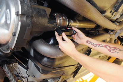
Figure 6
