 FREE 1 to 3-Day Delivery on Orders $119+ Details
Best Sellers


How to Install a Scott Drake Upper Control Arm Mount and Upper Control Arm on Your 2005-2010 Mustang
Installation Time
2 hours
Tools Required
- 13mm, 18mm, and 21mm Sockets
- 1/2" Drive Ratchet Wrench
- Torque Wrench
- Analog Protractor or Digital Angle Finder
- Two 1 1/8" Wrenches for Jam Nuts
- Torx Plus IP50 Bit
- Gloves
- Safety Glasses
- Jackstands
5R3Z-5500-BS
5R3Z-5500-MNT
TOOLS NEEDED FOR INSTALLATION
• 13mm, 18mm and 21mm Sockets
• ½” Drive Ratchet Wrench
• Torque Wrench
• Analog Protractor or Digital Angle Finder
• Two 1 1/8” Wrenches for jam nuts
• Torx Plus IP50 Bit
• Gloves
• Safety Glasses
• Jackstands (Tall enough to support gas tank)
Thank you for your purchase of the
Drake Muscle Cars Rear Lower Control Arms or Upper Control Arm Body Mount!
- WARNING! -
Always wear gloves and protective eye-wear when working around
automotive equipment
- WARNING! -
Always support a raised vehicle with jack stands.
- WARNING! -
Please review these instructions carefully. If any part of this procedure seems
out of your scope of capabilities, please seek a certified mechanic to perform
this installation. Failure to reassemble the suspension properly can lead to
serious injury
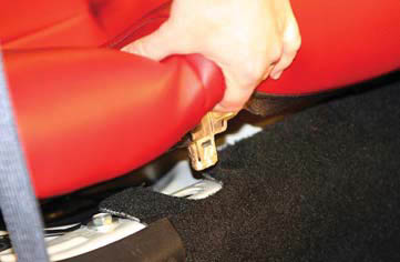
Figure 1
INSTALLATION
In order to access the upper control arm and body mount it is necessary to remove the assembly together. One of the bolts that retains the body mount is accessed under the rear seat inside the car. To access, remove the lower section of the seat by disengaging the two plastic clips located on each side in the front on the seat bottom. Once disengaged, lift up on seat cushion and remove. (See figure 1)
Locate the upper control arm body mount bolt at the center of the hump and remove using an 18mm socket. (See figures 2 & 3)
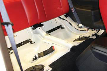
Figure 2
Make sure the emergecy brake is disengaged and raise the vehicle. Make sure to use jack stands if you are not using a lift. Support the center section of the rear axle with a jack to prevent from rotating after the control arm is removed.
At this point it is recommended to remove or lower the rear portion of the exhaust to get better access to the upper control arm mount. The rear muffl er mounts take a 13mm socket.
Using a 21mm socket on the nut, remove the upper control arm nut and bolt at the rear end housing. The rear end will shift once removed so make sure that it is supported adequately. Using an 18mm socket, remove the two remaining control arm mount bolts going into the body.
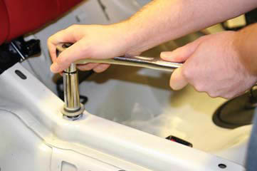
Figure 3
The control arm assembly cannot be removed without lowering the fuel tank. Support both sides of the saddle tank using caution to utilize a block or something with a larger surface area to prevent damaging the tank housing. Loosen the fuel tank staps at the rear of the tank using a 13mm socket (Some cars may be equiped with an unique 50 IP Torx head bolt which is an oversized T50 Torx bit available through Snap-On dealers under part number TX50TPE) Lower the tank far enough so that the upper mount and control arm can be removed together. (See figures 4, 5 & 6)
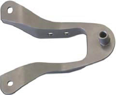
If reusing the factory body mount, disassemble the control arm from the mount using a 18mm and 21mm socket. It is recommended to upgrade the mount to the Drake Muscle Cars heavy duty mount as this is an extremely high stress point for the rear suspension.
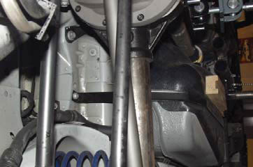
Figure 4
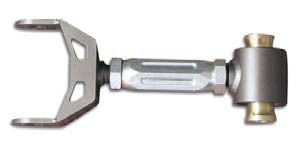
As a starting point adjust the Drake Muscle Cars control arm to the same length as the factory control arm.
Assemble the Drake Muscle Cars control arm to the body mount being used with the factory hardware and torque to 129 ft-lbs. The Drake Muscle Cars body mount has two mounting holes to change the instant center and therefore the ability to tune for anti-squat which is of high importance in drag racing applications. If unsure of how to calculate your particular vehicle’s requirement start with the rear most mount hole and compare track ET times between the two to get the optimal results. (See figure 7)
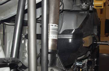
Figure 5
Bolt the new assembly into the car using the factory hardware. Torque the two under car bolts to 85 ft-lbs. (See figure 8)
Torque the bolt inside the car to 129 ft-lbs. Reinstall the rear seat.Position the fuel tank back into place and tighten the strap bolts to 38 ft-lbs.
Rotate the rear end housing until the mounting hole lines up with the rear mounting bracket of the contol arm and insert the factory bolt. Make sure the control arm mount is orientated with the support across the mounting bracket of the control arm facing up or it will come into contact with the rear end housing in jounce.
The vehicle must be at ride height before tightening the rear control arm bolt to the rearend housing. Raise the rear axle to ride height and torque bolt to 129 ft-lbs.
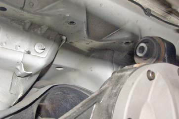
Figure 6
Adjust pinion angle on adjustable control arms. Lowered vehicles will require the pinion angle to be reset for optimal performance. Most cars like the following settings: Automatics 1-2 degrees negative and Manuals 2-3 degrees negative. Negative means the differential is pointed down in relation to the driveshaft.
The rear of the car needs to be resting on its own weight and sitting as close to ride height as possible on a level surface. Ultimately this can be achieved either by using drive on
ramps or lift that supports the vehcile on the tires. This can also be achieve with jack stands under the rear axle tubes and the front control arms
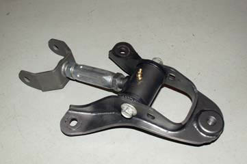
Figure 7
Using either an anolog protractor or digital angle finder (inclinometer) to measure the angle of the rear portion of the two piece drive shaft.
Measure the angle of the differential pinion flange. (See figure 9)
Subtract the pinion flange angle from the front driveshaft angle to find the net pinion angle.
Loosen the jam nuts on the new control arms to lengthen or shorten the arm as necessary to achieve the correnct pinion angle. Make sure to adjust both lower arms equally. Once the desired pinion angle is achieved, tighten the jam nuts. It is recommended to use blue Loctite on jam nuts before final tightening.
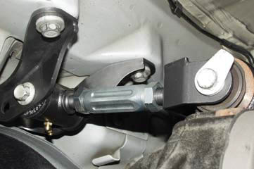
Figure 8
Make sure to double check the pinion angle after everything is tightened down.
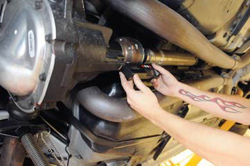
Figure 9
