 FREE 1 to 3-Day Delivery on Orders $119+ Details
Best Sellers


How to Install Sniper Sniper Fabricated Intake Manifold - Black on your Mustang
Installation on Modified Engine ComponentsHolley Sniper and Holley Sniper
EFI intake manifolds are designed to provide maximum performance for racing engines. The intake manifold will have the best fitment when the engine block and cylinder heads are machined to standard OE dimensions. If the engine block or cylinder head deck surfaces have been milled significantly, the alignment of the mounting bolt holes and the port flange openings to the cylinder head may be shifted and not match-up satisfactorily. If your engine has had the cylinder head or engine block deck surfaces milled, the following steps may be necessary for proper intake manifold installation.
The bolt holes in the intake manifold may have to be slotted to allow the fastener to properly pass through the manifold mounting holes.
The mounting fasteners must be freely threaded into the cylinder head while passing through the mounting holes or the manifold may not seat properly onto the cylinder head surfaces when the fasteners are tightened.
As the O-Ring grooves are located in the intake manifold mounting flanges, material may not be removed from the intake manifold mounting flanges without jeopardizing the sealing of the manifold. Any material removal required to align the port flange openings should be removed from the cylinder head, not the intake manifold,
When port matching the intake manifold port openings to the cylinder head openings, care should be taken not to break into or damage the O-ring groove or the O-ring seal will not be effective. The intake mounting surfaces on the cylinder heads should be in good condition, free of nicks or scratches, where the sealing O-rings will seat to ensure proper sealing. Installation of the Intake Manifold-
1. Before installing the intake manifold base, perform a test fit of the intake manifold without the O-Rings installed. Make sure that the mounting studs supplied can thread freely into the cylinder heads through the intake manifold mounting holes. The mounting flange should seat properly.
2. Check the port opening alignment. Test fit, fuel and vacuum plumbing, throttle linkage, wiring, etc. to ensure there are not any fit issues before performing the final intake manifold installation.
3. For final installation, install the eight (8) O-rings provided in the mounting flange O-Ring grooves. To make sure the O-Rings do not fall from the grooves, apply a light coat of grease to the O-Rings.
4. Install the mounting studs into the cylinder heads. Apply engine oil to the threads and thread in the stud until all of the threads are engaged by hand.
5. Put the intake manifold into place on the mounting flange. Be sure that all of the O-Rings are still in the grooves and are not being crushed between the flanges. WARNING! Threads in the aluminum cylinder head will not withstand abuse. Care must be taken to have proper thread alignment engagement and to tighten the fasteners to the proper specifications.
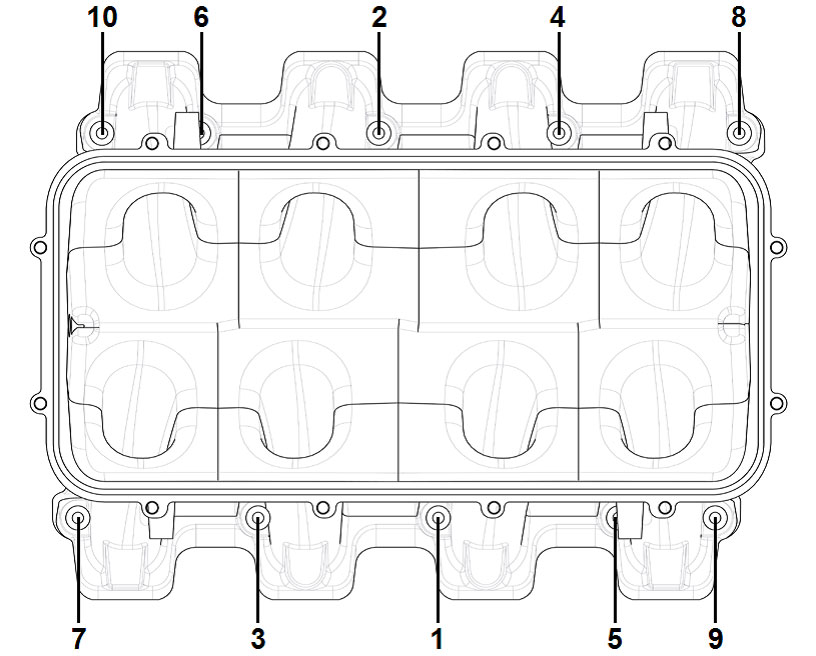
6. Install the washers and bolts provided (engine oil should be applied to the threads). Gently tighten the bolts working side to side and out from the center (see the following tightening sequence diagram), until manifold is seated on the mounting flanges and the O-Rings have been compressed. In two steps, tighten the mounting nuts first to 50 in-lbs. and then to 106 in-lbs. following the recommended sequence diagram.
7. On the underside of the Intake Manifold plenum area, there is a flange with (4) holes tapped. (1) 1/4” NPT and (3) 3/8” NPT fittings are provided. These ports will provide ample vacuum port sources for both carbureted and EFI manifolds. Any of these ports can be utilized depending on required needs. Any unused ports can be easily plugged or NPT fitting can be capped for later use as needed.
Installation of the Fuel Rails –
1. Apply a silicone lubricant to the O-Ring on the inlet end of the fuel injectors and insert the fuel injectors into the ports in the fuel rail. To insert the injector without tearing the O-Ring, gently rock the injector in the inlet of the port while applying pressure to insert the injector.
2. Position the injectors to properly orient the wiring plugs, apply silicone lubricant to the injector outlet O-rings, and insert all four injectors into the injector bosses in the base intake manifold applying gentle downward pressure onto the fuel rail. The proper orientation for the fuel rails is with the Holley Sniper logo facing outward.
3. Once the injectors are inserted into the intake manifold, place the washers on the supplied socket head cap screws.
4. Apply a drop of oil to the socket head cap screws, place the spacers between the fuel rail and the mounting bosses, and thread in the socket head cap screws.
5. Tighten the fasteners in two steps – 75 in-lbs. for the first step and 130 in-lbs. for the second step.
6. Check and make sure the injector is floating on the O-ring. Rotate the injector back and forth to confirm that there is no load on the injector body.
7. The fuel rail is designed to provide enough flow and volume to dampen fuel pressure oscillations and variations at the inlet of the fuel injectors. The fuel rails are machined to receive the supplied (AN-8) fittings for the ends of the fuel rails and the supplied (AN-8) crossover braided hose with (AN-8) fittings on either end.
Plumbing Information/Tips:
For engine power levels below 750HP, AN-6 (3/8”) plumbing to and from the fuel rails should be sufficient.
For power levels above 750HP, AN-8 (1/2”) plumbing is recommended
It is always recommended to only use tubular hose ends when a non-straight hose end is required.
The best and recommended configuration for plumbing the fuel rails is to split from the supply line with a “Y” type distribution block or fitting, then feed into the inlet end of each fuel rail. The hoses from the exit end of each fuel rail would then feed into each inlet port of a fuel pressure regulator with two inlet ports or into another “Y” type distribution block or fitting connecting to a hose leading to the fuel pressure regulator. Installation of the Carburetors or Throttle Bodies – 1. When installing Carburetor(s) or Throttle Body(s) and the connecting throttle linkage, check to be sure that all throttle levers and linkage components have adequate clearance from the intake manifold and plenum top. 2. The plenum tops for the 1 x 4150 and 2 x 4150 carburetor configurations do not have bosses for the mounting of throttle linkage. A bracket will need to be fabricated by the user for the particular linkage being used. 3. For all Holley Sniper EFI 92mm and 102mm throttle body mounting flanges, bosses on the side of the throttle body flange for the mounting of a throttle cable bracket. The bracket may need to be fabricated by the user for each individual throttle cable and throttle body application. It should be noted that the throttle body flange may work with a GM LS3 or Ford Coyote drive-by-wire throttle body.
