 FREE 1 to 3-Day Delivery on Orders $119+ Details
Best Sellers


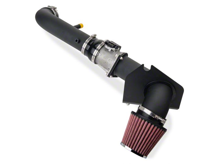
How to Install a SR Performance Cold Air Intake on Your 1996-2004 GT Mustang
Installation Time
1 hours
Tools Required
- 10MM wrench/socket
- 8MM wrench/socket
- 11MM wrench/socket
- Flathead Screwdriver
Shop Parts in this Guide
Installation
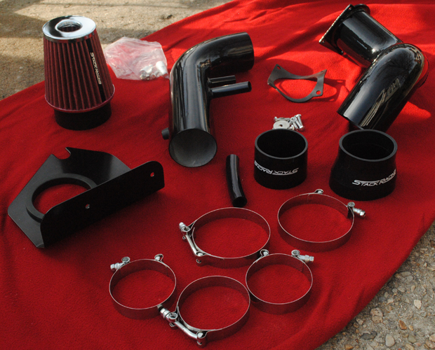
Included Parts:
- (1) 3” Straight Through Coupler
- (1) 3.5” – 3” Step Down Coupler
- (3) 65mm – 89mm Hose Clamp
- (2) 78mm – 101mm Clamp
- (1) Gasket
- (2) Anchor
- (6) Nylon Lock Nut
- (6) 1” Bolt
- (6) Small Washer
- (2) Large Washer
- (1) 4” Hose
- (1) Fender Shield
- (1) Cone Filter with Open End
- (1) 3.5” Pipe
- (1) 3” Pipe
Installation Instructions:
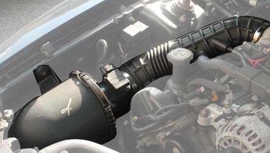
1. Disconnect all the hoses connected to the intake.
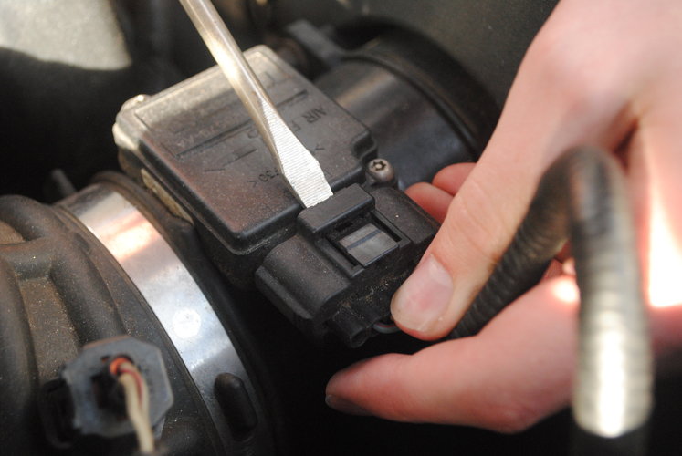
2. Remove the Mass Air Flow connection by inserting a flathead screwdriver into the clip and pulling apart.
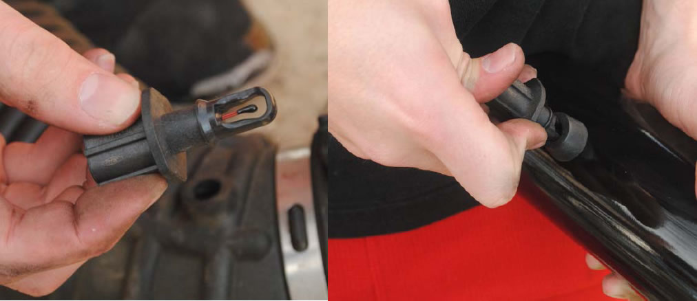
3. Unhook the Intake Air Temperature (IAT) Sensor connection.
4. Remove the bolt that attaches the air filter housing to the body of the vehicle. An 8MM wrench/socket can be used to remove this bolt. Save it, you will need it when you mount the new intake onto the vehicle.
5. Remove the clips that seal the air filter housing.
6. Detach all hoses that are connected to the current intake system. For Mustang GT models, there should be (2) hoses to remove.
7. Loosen the hose clamp that is attached to the throttle body on the engine. This will allow you to remove the entire intake assembly. Use a flathead screwdriver to loosen the clamp on the throttle body.
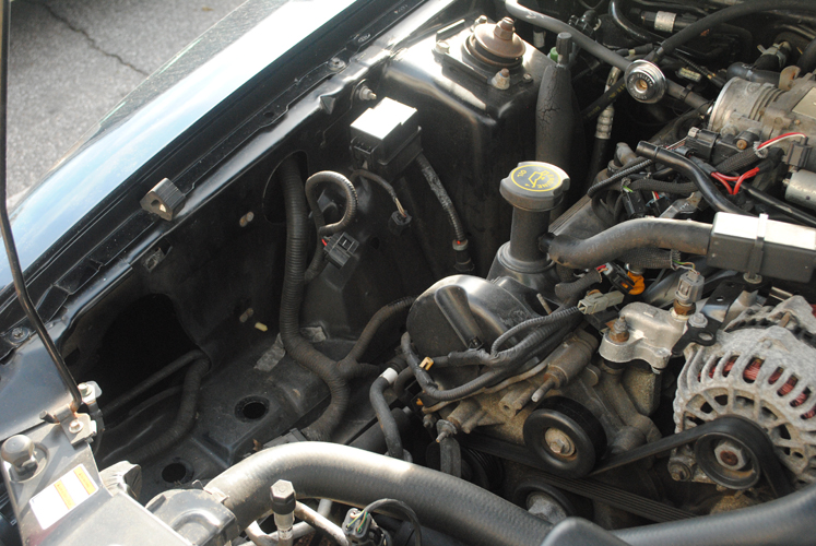
8. Remove the entire intake housing from the vehicle. This may require some wiggling and twisting, but it shouldn’t be too hard to remove from the car.
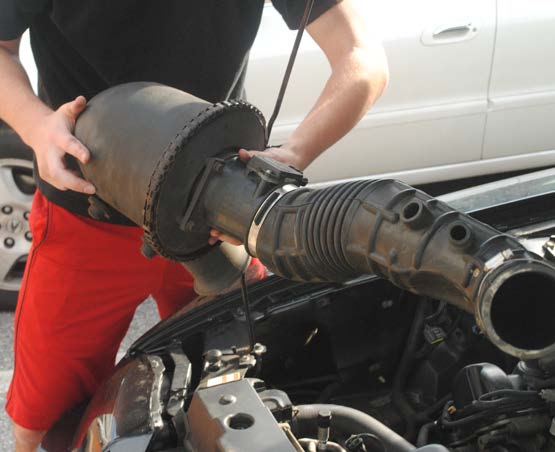
9. There should be (2) rubber grommets with the old intake housing that you removed. They may stay in place, but if they stay attached to the assembly, be sure to remove them and put them back onto the vehicle.
10. Attach the smaller 3” coupler to the throttle body. Once the coupler is attached, slide on the (2) smaller (65mm-89mm) hose clamps.
11. Tighten (1) clamp down on the throttle body. You will need the 10mm socket/wrench. Be sure to leave the other clamp loose. You will need to tighten this clamp down once you have the 3” pipe in place.
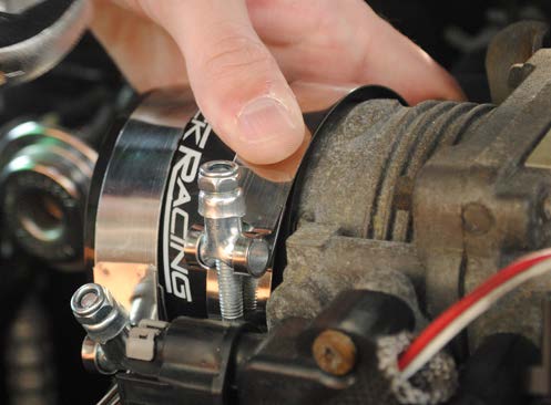
12. Before you install the new 3” Stack Racing intake into the vehicle, remove the intake air temperature sensor from the old housing. Install the sensor in the rubber mount on the new 3” intake pipe.
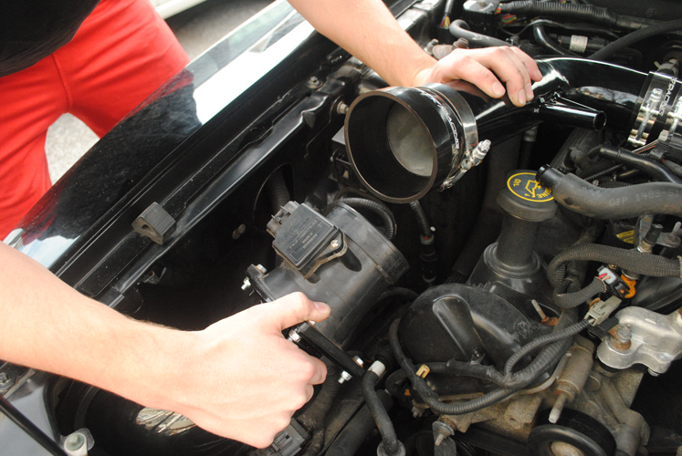
13. Take the upper 3” pipe and twist it into the coupler you installed on the throttle body. Twisting the pipe into place will insure a tighter fit.
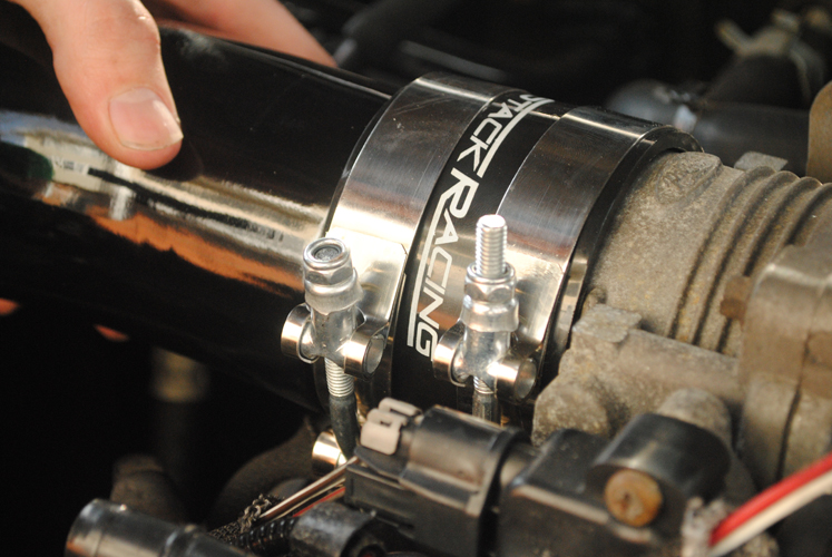
14. You can tighten the clamps, but leave them loose enough to ensure adjustability. Later in the process, you will need to adjust the pipes position in order to fit the rest of the assembly into the vehicle.
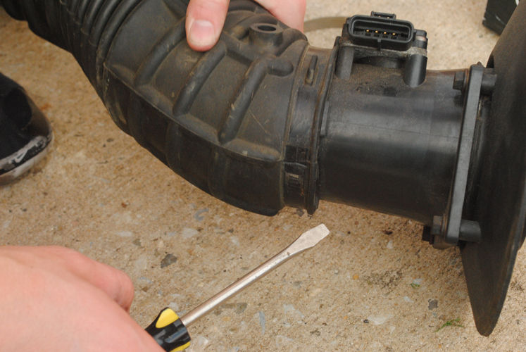
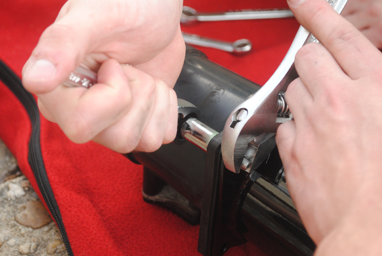
15. You will need to remove the Mass Air Flow Sensor from the original intake. It is hidden inside the original airflow tubing. You can get to the sensor by using a twisting motion with flat-headed screwdriver. Twist between the tubing and the sensor to remove the part. Be careful, as the sensor is an expensive and fragile piece.
16. Remove the (4) bolts around the base of the sensor and you will have the part you need.
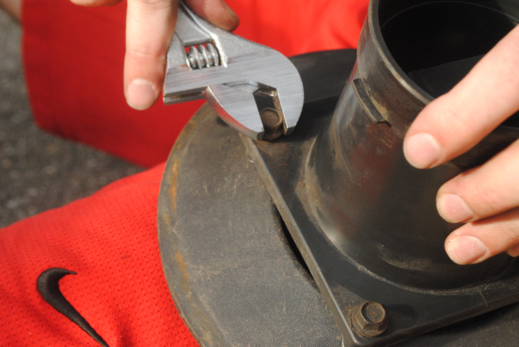
17. Using the parts provided in your kit, use an 11mm socket or an adjustable wrench to assemble the Mass Air Flow sensor to the kit’s 3.5“ pipe. Be careful not to tighten the bolts too much or you will crack the MAF’s housing. You will need the gasket, (4) 1” bolts, (4) Nylon Lock Nuts and *4) Small washers for assembly.
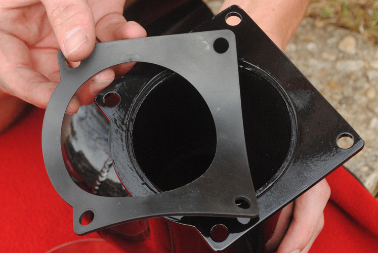
18. Install the fender shield with the angle edge facing the tube.
19. Next, attach the filter to the end of the tube using a provided clamp. Tighten the clamp now because once the filter is installed within the fender, you wont have access to the clamp again.
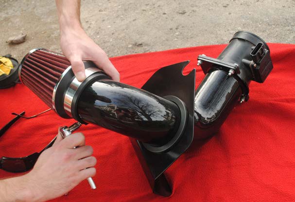
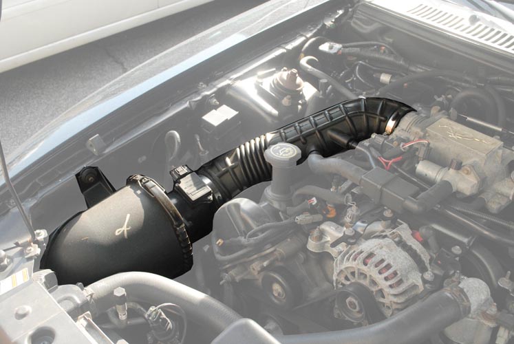
20. Slide the bottom half of the assembly into the fender, filter first.
21. Reuse the rubber mount from the original intake to attach the plate to the vehicle using the original bolt.
22. Use the second coupler and remaining hose clamps to secure the assembly together. The larger end of the coupler will go on the mass air flow side while the smaller end will go to the 3” pipe. Make sure to tighten the clamps to get an air tight fit.
23. Make sure to do a double check on all bolts and clamps to make sure they are airtight.
24. Reconnect all wiring harnesses and hoses.
25. Start the engine. Make sure the car idles smooth and no check engine lights are on. If they are, you may have a loose clamp or wiring harness.
Installation Instructions written by AmericanMuscle customer Travis Walters 3.30.12
