 FREE 1 to 3-Day Delivery on Orders $119+ Details
Best Sellers


HOW TO INSTALL AN SR PERFORMANCE LINE LOCK - BURNOUT CONTROL KIT (2010-2014 ALL)
Installation Time
2 hours
Tools Required
- 7/16” wrench
- 16mm and 11mm wrench
- Teflon tape
- 9/16”socket
- 13mm socket and extension
- clean rags
- 15mm wrench
- 16mm wrench
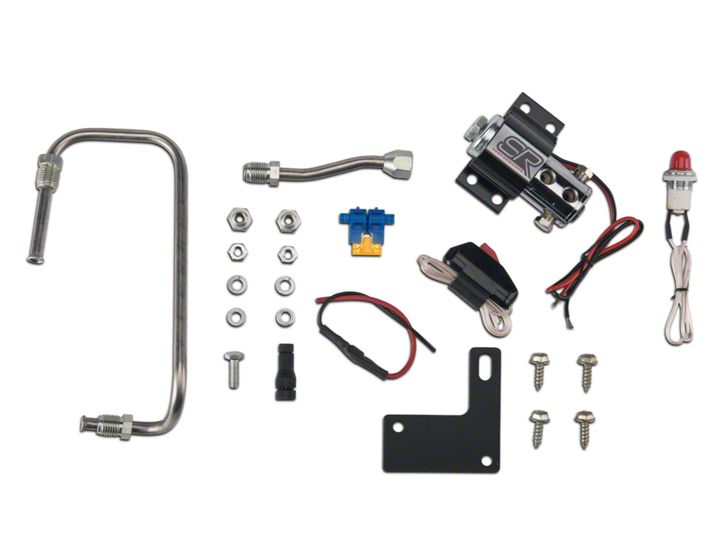
Shop Parts in this Guide
-1.png)
IMPORTANT: Prior to attempting installation, please carefully read through the instructions to familiarize yourself with the procedures and steps required. It is important to note and for you to understand these instructions contain specific cautions and warnings that must be followed to prevent the chance of improper installation. Incorrectly installing the GMS Tyre Fryer could potentially render the vehicle unsafe to drive. If this is your first time installing a unit such as this, please show extreme caution or consult a professional certified automotive mechanic
INSTALLATION NOTES: When working around brake systems cleanliness is imperative to avoid fluid contamination. This SR Performance Line Lock solenoid valve is installed into the front brake system for momentary brake holding. When properly installed and operated in accordance with directions provided the solenoid valve will not interfere with normal brake operations.
-2.png)
STEP 1. Clean the area around the mounting location. One way is to blow compressed air around the area to quickly clear a path for easy installation. Using the pictures provided identify the location where the system will be mounted as well as the front brake line to the Master Cylinder.
STEP 2. Position and attach the supplied mounting bracket to the solenoid as shown in step 2 and 3.
Using a 7/16” wrench, Install one each of the supplied 1/4-20 bolt, 1/4” flat washer, 1/4” lock washer, and 1/4-20 nut into each hole and fully tighten.
Note: A few drops of red Loctite insure a secure long lasting mount.
STEP 3. Using a 16mm and 11mm wrench, Install and tighten the provided adapters and plugs into the solenoid as shown in figure 3.
NOTE: Always use Teflon® tape to ensure a leak-proof seal. The use of thread sealer paste is ordinarily not recommended because it contaminates the brake fluid. Ensure the solenoid body does not loosen while tightening adapters and plugs. It is important to make sure the ports are correctly aligned and positioned before using a 9/16”socket to re-tighten top solenoid nut.
-3.png)
STEP 4. Review photo 4 shown above to make sure you understand the proper new brake line routing before you move to the next step. DO NOT connect brake lines to solenoid just yet.
NOTE: There is no need to use Teflon® tape on flare fitting threads. They are designed to seat and be leak free.
STEP 5. Using a 13mm socket, Remove left Master Cylinder nut from Master Cylinder. A ratchet and extension really help here.
STEP 6. For Mustangs with the Induction Tube (highlighted on the left), this should be disconnected and removed for easier access to the brake lines. Once installation is complete it can be reinstalled.
STEP 7. Located on the side of the strut tower, remove front brake line from the brake line clip. See Figure 7.
STEP 8. Before removing the factory brake line from the rear body of the Master Cylinder, place clean rags underneath to catch residual leakage. Fluid that may spill onto the vehicle needs to be cleaned and removed immediately. Now, using a 15mm wrench, you may unscrew front brake line shown in figure 8.
-4.png)
STEP 9. Our Recommended Installation Procedure: Thread the SR Performance Line Lock brake line into theOEM front brake line by hand and leave loose at this point. This allows for slight movement of lines while making adjustments. While finger tight, thread the SR Performance Line Lock brake line into the adapter. Gently push theOEM brake line slightly down to allow the mounting bracket hole to match up with the Master Cylinder stud.
Note: Minor adjustments (bending/flexing) of lines may be required for perfect alignment).
Once the lines are properly positioned, using a 15mm wrench on the brake line nut and a 16mm wrench on the adapter side, tighten all the flare fittings.
-5.png)
STEP 10. Our Recommended Installation Procedure: Following the same procedure as above, thread the SR Performance Line Lock brake line into the Master Cylinder, but not tight enough to where it cannot be adjusted. Threadthe SR Performance Line Lock brake line into the adapter, finger tight as well.
Note: Minor adjustments (bending/flexing) of lines may be required for perfect alignment).
Once line is aligned, tighten all flare fittings.
Caution: NO NEED TO OVER TIGHTENING. IT MAY CAUSE LEAKS.
STEP 11. Using your 13mm socket and extension, Reinstalled the Master Cylinder nut removed and tighten to the factory spec of (18ft.-lbs).
STEP 12. You’re almost there! Before you try it out there are a few more steps that need to be adhered to.
1.Bleed ALL brakes by following manufacturer’s service manual guidelines (front brakes will usually have the most airbut do them all back to front.
2.Make sure all the fittings are fully secured.
3.Confirm there are no leaks present.
4.The brake pedal should be firm with a solid feel. If the brake pedal slowly falls to the floor, there is a brake fluid leakand/or still air in system. Check and re-bleed if necessary.
WARNING - Do not operate vehicle if leaks and/or air are in the lines!
WIRING INSTALLATION
NOTE: The SR Performance Line Lock system is designed and intended for 12 volt usage only. Only an armingswitch is included in this kit. If wired properly that is all you need. Some people like to add an on/off (activation) switch as well. It acts as a bypass so no one can play with it.
Before attempting to do the wiring it is always recommended you disconnect the negative (-) battery terminal. When wiring this system use #18 gauge or better standard insulated automotive wire to insure good electrical connections and continuity. A fuse holder with a 4-amp fuse is provided (See wiring diagrams for wiring details. The fuse can protect the electrical system in the event of a short circuit and therefore should be installed. We also provide one way diode that is to be installed under the dash to eliminate the chance of reverse voltage.
-6.png)
STEP 13. You must properly ground the black wire from the line lock solenoid. For this install, we installed the groundat a spot near the firewall for easier wiring. See Figure 13 with circle.
STEP 14. Pass the red wiring through one of the existing access points (one is located on the driver’s side firewall). Be sure to ensure the wires are not pinched or pressing against a sharp metal edge. You can see where we ran our wire in picture 14.
STEP 15. Locate the Blue/Grey brake pedal switch directly under the dash (below the steering column). Rotate the brake pedal switch clockwise 1/8” turn to remove.
Caution: It is important that you do not allow the brake pedal itself to travel while removing and/or re installing the brake pedal switch
-7.png)
STEP 16. You will note the 4 wire connector attached to the brake pedal switch. violet/red, black/blue yellow/green, and violet/white. You will need to remove a small portion of the electrical tape and convoluted tubing to expose and view the violet/white wire. (Be extremely careful not to cut wires).
STEP 17. Using the included T-tap connector, tap the black wire side of provided diode into the violet/white wire of the brake pedal switch. Connect the red wire side of the same diode into the momentary switch “in line” as shown in the wiring diagram using the provided 18ga connector / Scotchlok.
Note: Connecting the diode properly is a crucial step to insure your SR Performance Line Lock works properly. (See wiringdiagrams below) If installed backwards the system will not work and could cause AdvanceTrac malfunction. Additionally the diode needs to be down stream of the arming switch (as shown in the diagram) so that it only sees 12v reference when the SR Performance Line Lock is armed otherwise it could cause the AdvanceTrac to malfunction.
Once wiring on steps 16 and 17 are complete, reinstall the brake pedal switch
STEP 18. Tap into a 12V accessory/cigarette lighter socket wiring harness connection with provided Scotchlock connector or another appropriate 12V source. Insure the 12v source is only “hot” when the key is on.
STEP 19. Reconnect negative battery cable and turn ignition key to the “ON” / engine “OFF” position. While the car is at rest, with the parking brake on, repeatedly tap your arming switch. You should hear the SR Performance Line Locksystem clicking on and off as you tap the button. NOTE: Do Not depressing your brake pedal while initially test the solenoid.
If the solenoid is not “clicking” check all connections and the supplied in line fuse for a short and correct any problems before moving to the next step.
CAUTION: Before attempting to drive the vehicle, please check the brake system for proper operation. Confirm all your connections while under pressure to make for certain there are no leaks and be sure that you have solid firm brake pedal. On a flat level surface, Test the system several times to be sure that it operates correctly. Make sure the front two wheels have the brakes engaged when the solenoid is activated and that all four wheels are free to rotate when the system is not engaged.
OPERATION INSTUCTIONS
To actuate the SR Performance Line Lock (BURNOUT):
STEP 20. Before doing a burnout, you must turn OFF your Traction Control/AdvanceTrac while at a complete stop.
1.While remaining motionless, depress and hold the brake pedal.
2.Press the Traction Control / AdvanceTrac button for 5 sec until “AdvanceTrac OFF” dash light appears.
3.With the Traction Control/AdvanceTrac OFF, fully depress and hold the brake pedal.
4.Activate the momentary switch of the SR Performance Line Lock system.
5.Release the brake pedal.
6.The front brakes should now be locked and the rear wheels un-locked and free to spin.
7A. – Automatic Transmission Vehicles – Quickly step on the gas pedal aggressively to get the rear wheels spinning and hold at the desired RPM.
7B. – Manual Transmission Vehicles - Raise the engine RPM speed to a moderate level (Approximately 4500 RPM or higher) and quickly but smoothly release the clutch pedal fully.
Your rear wheels should now be spinning and the vehicle should not be rolling forward if all the above steps have been performed correctly.
8.Fan the gas pedal to control the amount of wheel spin.
9.Once rear tires are heated, release the momentary switch to allow the vehicle to “drive-out” of the burnout.
10.Be prepared for the vehicle to lunge forward and get traction.
11A. – Automatic Transmission Vehicles – Quickly take your foot off the gas and press the brakes to slow down.
11B. – Manual Transmission Vehicles – Be prepared to re-depress the clutch and brake pedal to slow down.
Turn ON your Traction Control / AdvanceTrac when not using the SR Performance Line Lock.Warning: Turn ON your Traction Control / AdvanceTrac when not using the SR Performance Line Lock.Performing a burnout without the Traction Control / AdvanceTrac off can damage the vehicle because the ABS is trying to counteract your burnout. AdvanceTrac would stop the burnout and a “Service AdvanceTrac” dash light might turn on. If this occurs, turn off car to reset system and/or take it to you nearest Ford dealership to reset the ABS hard code.
WARNING: SR Performance Line Lock is not designed to act as a long term parking brake. It isdesigned to hold for no more than 30 seconds. The SR Performance Line Lock is recommended foruse during closed track events and competitive driving venues ONLY! Consult your local
-8.png)
Best Sellers
Related Guides
-
Installation
-
Installation
-
Installation
