 FREE 1 to 3-Day Delivery on Orders $119+ Details
Best Sellers


Install Guide for a Stainless Works Long Tube Headers and High Flow Catted X-Pipe Kit (2011-2014 GT)
Shop Parts in this Guide
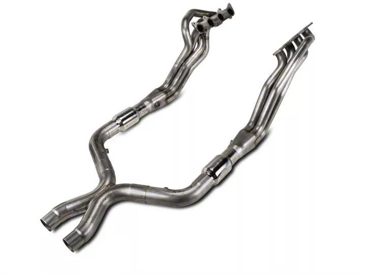
INSTALLATION INSTRUCTIONS FOR 2011 MUSTANG GT 5.0 HEADERS AND LEADPIPES – P/N M11HDRCATX/ M11HDRORX
Thanks for purchasing Stainless Works Muscleflow Headers for your 2011 Mustang GT 5.0. We have gone to great pains to make sure that our exhaust systems fit and sound great. Please follow these steps to ensure that your installation goes as planned.
1. Stainless Works recommends the use of Permatex Hi-Temp RTV silicon gasket maker as an option to or in conjunction with the use of factory gaskets. The recommended RTV is Sensor-Safe P/N 101BR or 27BR, available at NAPA and other retailers.
2. Disconnect the battery before starting work on the exhaust system for your vehicle. Reconnect the battery when the job is completed.
3. Your exhaust system can be installed by a weekend warrior but the use of a lift is recommended for ease of installation. If using a jack, the vehicle must be placed on a level hard surface and jack stands are required for safety reasons.
4. Raise and support vehicle.
DISASSEMBLY
5. Remove (4) 10 mm nuts and cross brace at rear of K member.
6. Remove (3) 6 mm bolts holding engine service cover on.
7. Remove (2) 10mm nuts and (2) 10mm bolts at rear of front crossmember brace.
8. Loosen (4) 10mm bolts at front of front crossmember brace until engine service cover can be removed.
9. Remove H-pipe by loosening clamps at front and rear, save clamps at rear of Hpipe for installation of Stainless Works system.
10. Remove 02 sensors from catalytic converter pipes and remove (4) 10mm nuts, (2 per side), and remove catalytic converter pipes.
11. Remove battery and battery box (3) 6mm bolts to allow easier access to bolts on manifold.
12. Mark steering shaft (to aid in later reassembly to the same position) and remove 8mm bolts at lower U joint on steering shaft and disconnect steering shaft and secure out of way.
13. Remove O2 sensors in the manifolds.
14. Remove wires and (3) 8 mm blots from starter and remove starter.
15. Remove 10 mm nuts from motor mounts. 16. Raise engine off mounts approx. ¾” high.
17. Remove (4) 10 mm bolts and studs holding left motor mount to engine and remove motor mount.
18. Remove (2) 10mm nuts and (4) 10mm bolts and studs holding right motor mount to engine and remove mount.
19. Remove (16) 10 mm nuts (8 per side) holding manifolds on and remove.
ASSEMBLY
1. Install left side O2 extension into wiring for front O2 for header (easier to do now). Ziptie the connections at both ends to assure that they will not separate. This will prevent any problems with a check engine light (CEL).
2. Apply sensor safe silicone to face of header flanges and install using 10mm nuts removed from manifolds.
3. Re-install motor mounts (Do not lower engine at this time).
4. Re-install starter, steering shaft, and rear cross brace (must be done before lowering engine).
5. Now lower engine and re-install motor mount nuts.
6. Install front O2 sensors and wiring (may have to re-route wires). On automatic, check to make sure to route wires behind shift linkage mount on transmission.
7. Install catalytic converters or off-road pipes with 3” clamps.
8. Install lead pipes into X-pipe then onto cats or off-road pipes using (4) 3” clamps and factory clamps. 9. Install rear O2 sensors into leadpipes.
10. Adjust everything for fitment and tighten all clamps.
11. Be sure to have adequate clearance around all wires, hoses and lines. If anything is in contact with the exhaust system, it will melt. Make sure to have at least ½” of clearance and wrap any suspect areas with DEI thermal barrier wrap.
12. Lower vehicle.
13. Re-install battery and battery box.
14. After double checking for clearance and making sure all lines, wires and hoses are secured, drive the car for 10-20 miles and re-check all clamps and clearances. Your system may be tack welded at the joints/ clamps to reduce shifting of the system during heating and cooling cycles. Make certain to disconnect the battery before performing any welding.
