 FREE 1 to 3-Day Delivery on Orders $119+ Details
Best Sellers


Steeda IRS Roll Steer Kit ('99-'04 Cobra) - Installation Instructions
Installation
1. Locate the car on level ground and measure the distance from the center of the rear wheel to the vertical edge of the fender lip for both sides. Roll the car back and forth a couple of times to settle the suspension before taking this measurement. Write these measurements down for future reference.
2. Jack the car up and place it on jack stands. It is important to get the car as level as possible, both front- to-back and side-to-side. Consult your owner's manual for proper jacking points. Do not jack the rear of the car up under the differential as is common with a solid axle. The Cobra IRS is not designed to support the weight of the car at this location. Failure to follow this warning can result in damage to the axle assembly.
3. Remove both rear wheel/tire assemblies.
4. Disconnect the bolt that secures the emergency brake cable to the lower control arm. This will make removal and installation of the springs easier.
5. Jack the lower control arm up slightly and disconnect the damper. Generally it is easier to perform this installation if the damper is completely removed.
6. Using the proper spring compressor, remove the rear springs. It may be necessary to disconnect the stabilizer bar in order to affect enough rotation in the control arm to remove the spring. There are other methods to remove the springs but not recommended for the novice mechanic.This can be a very dangerous procedure if not done correctly. If you do not know how to do this, have someone with the a requisite skills help you.
7. With the springs removed, re-install any suspension components you disconnected when removing the springs (except the damper).
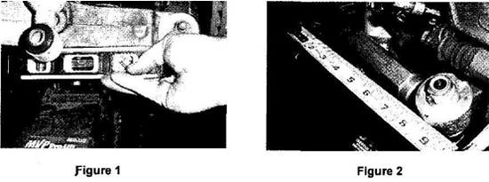
8. The outer tie-rods must be replaced with the included billet aluminum adjusting collar and rod end. Before removing the outer tie-rod it is important to measure the distance the mounted outer tie-rod is from a fixed location, usually the exhaust hanger. Jack the lower control arm up until it is level along the lower rear edge. (Note the exact location you have placed your level for duplicating the procedure for the other side.)Figure 1
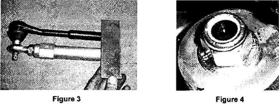
9. Using a tape measure or metal ruler, mark a location on the knuckle and note the measurement as well as the exact location of the tip of the ruler. You will use this reference point when re-assembling the system.Figure 2(installed kit shown)
10. Remove the cotter pin and slotted nut that holds the outer tie-rod to the spindle. Disconnect the tie-rod from the IRS knuckle. It is important to use a tie-rod removal tool for this procedure. Tapping the side of the knuckle with a hammer to loosen the tie rod, as is a common practice, will damage the soft aluminum knuckle and cause premature failure.
11. Loosen the jam nut that locks the outer tie-rod to the inner tie-rod. Do not back the nut far away from the outer tie rod. Back it off just enough so it is no longer contacting the outer tie-rod.
12. Unscrew the outer tie-rod until it comes completely off.
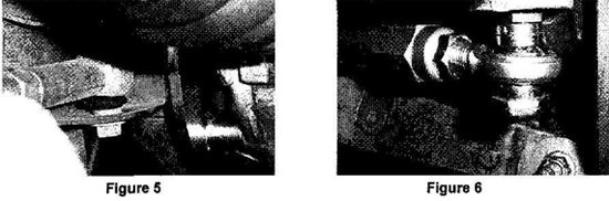
13. Using a straight edge, adjust the length of the billet collar and rod end assembly to approximate the factory tie-rod length.Figure 3
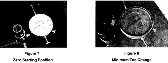
14. Insert the provided tapered stud into the knuckle. Install the hardened washer and nylon insert nut and torque to 47 Nm {35 Ibf-ft)Figure 4
15. Thread the billet collar/rod end assembly onto the inner tie rod until it contacts the jam nut. Slide spacers onto the exposed shaft of the rod end stud (installed in Step 1) that are approximately 3/8" thick, slip the rod end over the shaft with another spacer on the opposite side that will permit the tightening of the nut without threading into the nylon insert. This is done to provide for easy removal when making spacer changes to correct the roll steer without damaging the nylon insert.
16. Jack the control arm up to the same level position used in Step 8. Adjust the length of the new rod end assembly until it matches the length of the original outer tie-rod by duplicating the measurement as noted in Step 9. Tighten the jam nuts to secure the length of the assembly.Figure 2Be sure to check the alignment of the inner tie-rod and the outer rod end to verify they are in the same plane before tightening the jam nuts. If they are not in the same plane, they can be damaged as the suspension cycles through the normal motion. Figure 5 shows an inner tie-rod that is slightly misaligned with the outer rod end in Figure 6.
17. Repeat Steps 4 thru 16 for the other side.
Adjustment:
1. Before proceeding with the roll steer adjustments, it is important to check the toe alignment. This will require two jacks or a jack and one jack stand to check the alignment. Jack one control arm up and place a jack stand under, it so the center of the hub is the same vertical distance to the fender lip as noted in Step 1. Use the jack to raise the opposite control arm to the vertical height also noted in Step 1.
2. Re-install the wheel/tire assemblies.
3. With the help of a friend, measure the distance between the front and rear edges of the tires. Use the exact same location on the front and back to insure a good approximation (same tread edges). These measurements should be very close to identical, with a slight toe-in. If there is a significant variation, locate the wheel with the greatest deviation and adjust as necessary. Use common sense. If it does look or feel right, check it again.
4. Remove the wheel/tire assemblies and proceed with the roll steer adjustment.
5. Using a bump steer gauge, check the toe changes as the suspension is jacked up and lowered, two inches up and 2" down. You should start from the level centerline of the hub as your zero point, with the control arm raised so the hub-to-fender distance matches that measurement from Step 1.
6. Re-arrange the spacers between the rod end and the knuckle and repeat Step 22 until you have achieved the minimum toe change. This is a process of trial and error until you achieve the smallest possible toe change. It is often impossible to achieve absolute zero toe change and is generally better to arrange the spacers so that the car toes in slightly when the suspension is compressed.
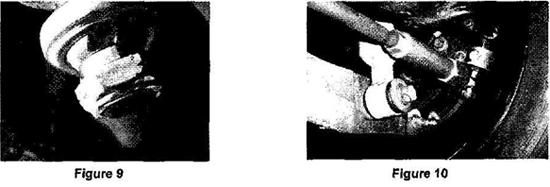
7. Once you have achieved minimum toe change, remove the nut on the base of the rod end stud, install a spacer that will allow at least 7/16" of exposed threads and re-install the nylon insert nut on the bottom of the stud. Torque the nut to 68 Nm (50Ibf-ft). Do this for both sides.Figure 9
8. Reset the toe setting following the procedure used in Steps 1 thru 4 of the "Adjustment" section.
9. Recheck every nut and bolt to insure all fasteners are properly tightened.
10. Re-install the springs and dampers, re-attach the emergency brake cable bracket and remove the car from the jack stands. The final assembly should look likeFigure 10
11. Test drive the car at slow speeds to insure all components are working properly.
12. Take the car to a quality alignment shop and have the car four-wheel aligned.
Installation instructions provided by Steeda
Best Sellers
Related Guides
-
Installation
-
Installation
-
Installation
