 FREE 1 to 3-Day Delivery on Orders $119+ Details
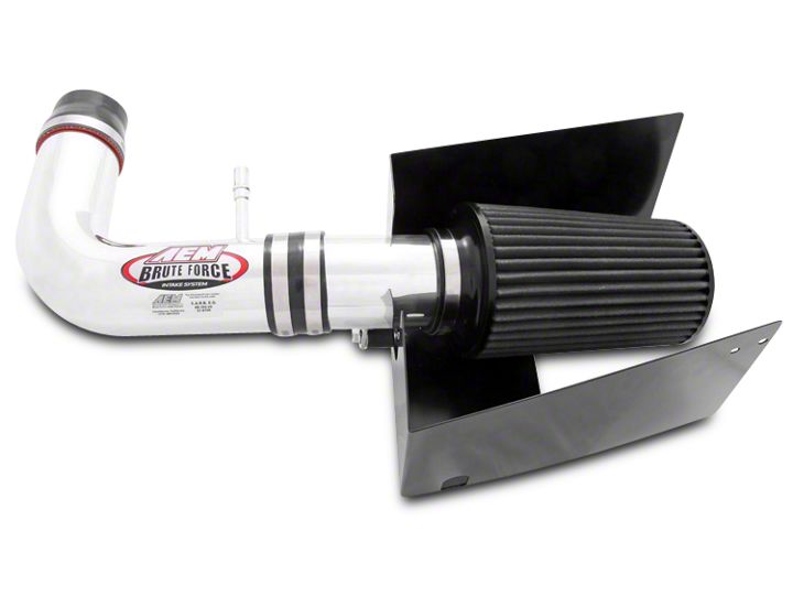
How to Install AEM Brute Force Cold Air Intake - Gunmetal Gray on your F-150
Shop Parts in this Guide
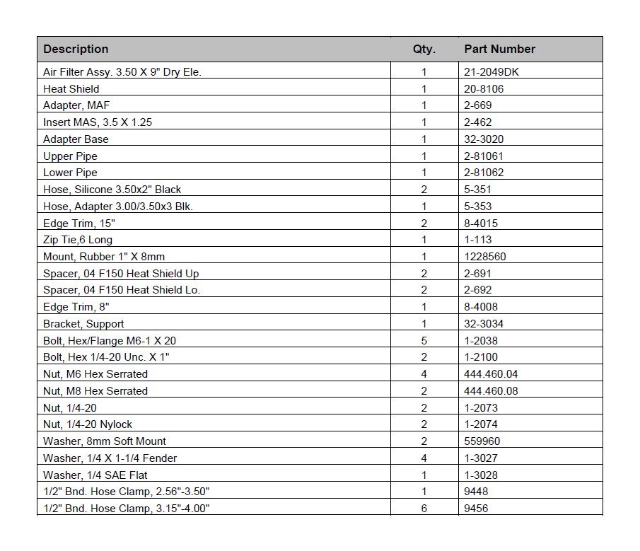
PARTS LIST
Read and understand these instructions BEFORE attempting to install this product.
Failure to follow installation instructions and not using the provided hardware may
damage the intake tube, throttle body and engine.
The AEM® intake system is a performance product that can be used safely during mild
weather conditions. During harsh and inclement weather conditions, you must return
your vehicle to stock OEM air box and intake tract configuration. Failure to follow these
instructions will void your warranty.
1. Preparing Vehicle
a. Make sure vehicle is parked on level surface.
b. Set parking brake.
c. If engine has run in the past two hours, let it cool down.
d. Disconnect negative battery terminal.
e. Raise the front of the vehicle with a jack. Refer to your owner’s manual for proper jack and jack stand placement to properly support vehicle. Support your vehicle using properly rated jack stands before wheel removal or while working under the vehicle.
NEVER WORK UNDER A VEHICLE WITHOUT USING JACK STANDS.
f. This intake system includes a replacement windshield washer system.
g. Do not discard stock components after removal of the factory system.
2. Removal of stock system
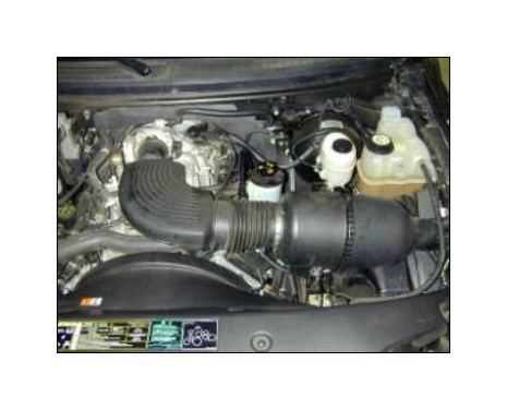
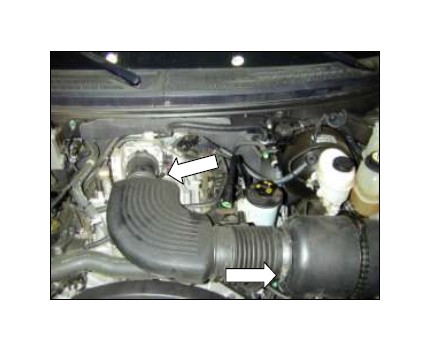
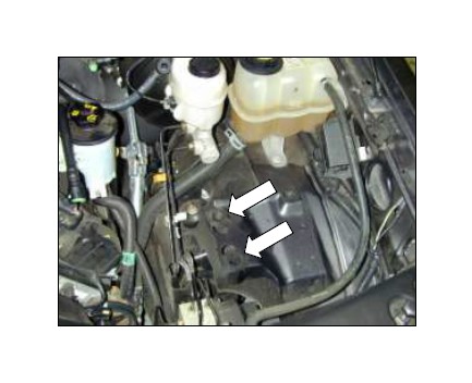
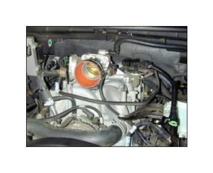
a. The engine bay should look like this.
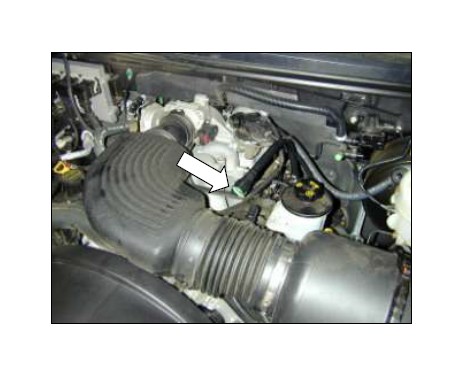
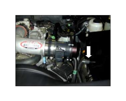
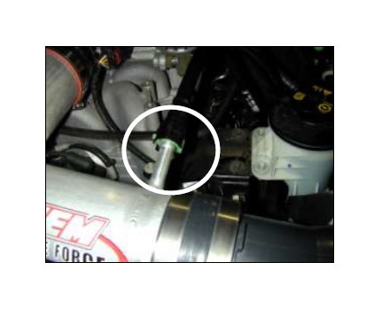
b. Unclip the plastic crankcase breather tube from the stock air inlet tube.
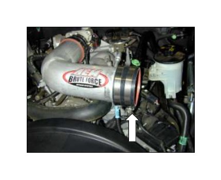
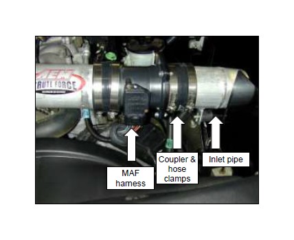
c. Loosen hose clamps at the throttle body and the air filter housing.
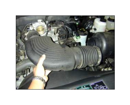
d. Remove upper inlet pipe.
e. Unclasp the clip holding the air filter element casing together.
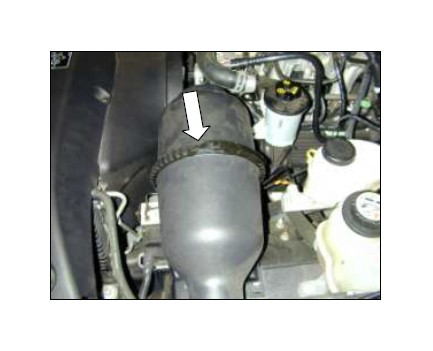
f. Gently pry open the housing at the any one of the tabs. Careful not to damage the MAF sensor.
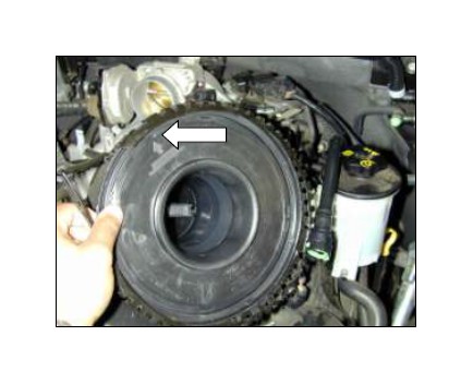
g. Disconnect the MAF sensor connector from the MAF sensor. Careful not to damage MAF sensor harness.
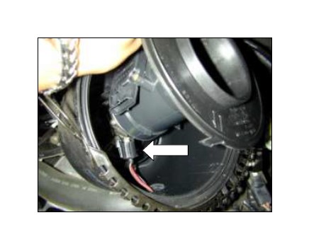
h. Loosen and remove the two screws holding the MAF sensor.
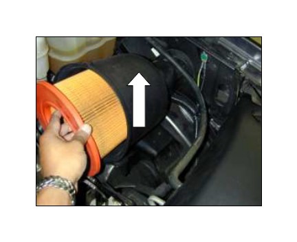
i. Remove filter element and housing. Gently pull up on the housing to remove.
3. Installation of AEM® intake system.
a. When installing the intake system, do not completely tighten the hose clamps
or mounting hardware until instructed to do so.
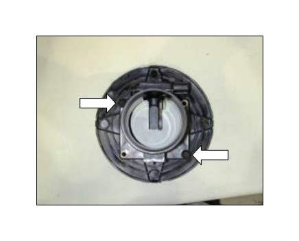
b. Remove rubber grommets left by the filter element housing.
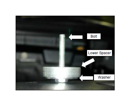
c. Assemble the following bolt, washer and lower spacer.
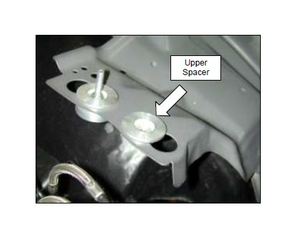
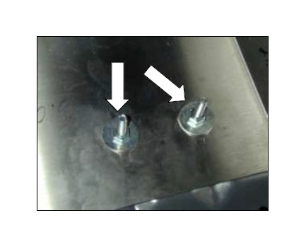
d. On the left is a fully assembled anchor for the heat shield. On the right, insert the upper spacer into the stock housing mounting surface.
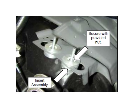
e. Insert the assembly from Step 3c into the upper spacer from underneath. Secure with provided nut.
f. Insert heat shield. Make sure the holes fit without stressing the anchor bolts. You may need to readjust for best fit. Secure third tab with provided bolt.
g. Secure the heat shield with the provided washers and Nyloc nuts.
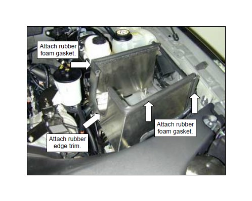
h. Attach rubber foam gasket material to the top of the heat shield and also to the front leg. Attach the rubber edge trim to the intake opening.
i. Attach the reducer coupler to the throttle body and secure with hose clamp #48. The other end should not be tightened.
j. Insert the upper inlet pipe into the coupler and secure.
k. Attach and secure the connecting coupler to the upper inlet pipe.
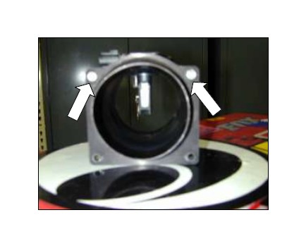
l. Attach the MAF sensor adapter to the MAF sensor. Secure the adapter with the M6 bolt and nylok nut only to the holes located nearest the sensor.
m. Insert the MAF sensor assembly into the coupler.
NOTE: Make note of the air flow direction.
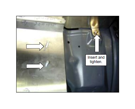
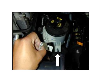
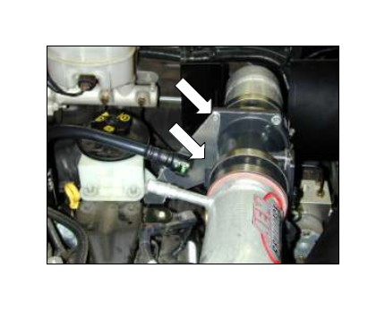
n. Remove the front bolt that secures the power steering fluid reservoir. Loosen the other two bolts. Place the MAF sensor bracket tab under the front tab of the power steering fluid reservoir. Secure mounting position, but do not fully tighten.
o. Insert rubber mount into the heat shield and secure with provided washer and nylok nut.
p. Re-attach the MAF sensor connector. Attach the last coupler to the MAF sensor assembly and secure with hose clamps. Insert the second inlet pipe and align with rubber mount.
q. Align the both inlet pipes along with the MAF sensor assembly to the bracket on the heat shield.
r. Secure the MAF sensor bracket to the remaining two holes on the assembly. Realign to the rubber mount and secure rubber mount to the pipe bracket. Check clearance through the heat shield.
s. Re-attach breather hose. Make sure connector snaps onto the nipple.
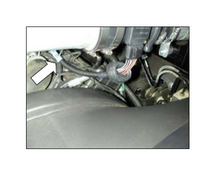
t. Secure MAF wire harness away from the fan with provided zip tie. Failure to do so may damage harness and may result in engine failure.
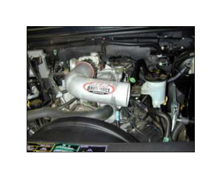
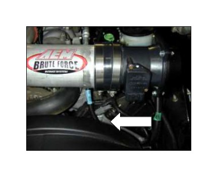
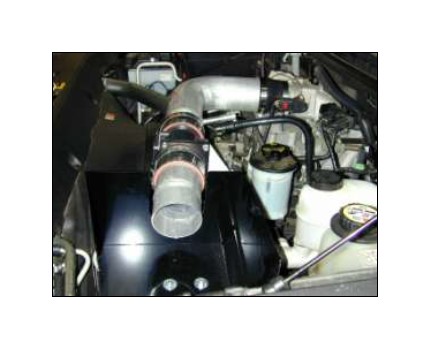
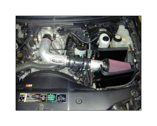
AEM® intake system installed
4. Reassemble Vehicle
a. Position the inlet pipes for the best fitment. Be sure that the pipes or any other components do not contact any part of the vehicle. Tighten the rubber mount, all bolts, and hose clamps.
b. Check for proper hood clearance. Re-adjust pipes if necessary and re-tighten them.
c. Inspect the engine bay for any loose tools and check that all fasteners that were moved or removed are properly tightened.
d. Reconnect negative battery terminals and start engine. Let the vehicle idle for 3 minutes. Perform a final inspection before driving the vehicle.
5. CARB Sticker Placement
a. The C.A.R.B. exemption sticker, (attached), must be visible under the hood so that an emissions inspector can see it when the vehicle is required to be tested for emissions. California requires testing every two years, other states may vary.
6. Service and Maintenance
a. It is recommended that you service your AEM® Dryflow™ filter every 20,000 miles for optimum performance. Use AEM Dryflow cleaning kit part # 21-110.
b. Use aluminum polish to clean your polished AEM® intake tube.
c. Use window cleaner to clean your powder coated AEM® intake tube. (NOTE: DO NOT USE aluminum polish on powder coated AEM intake tubes).
