 FREE 1 to 3-Day Delivery on Orders $119+ Details
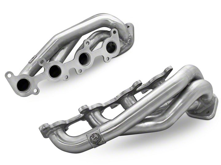
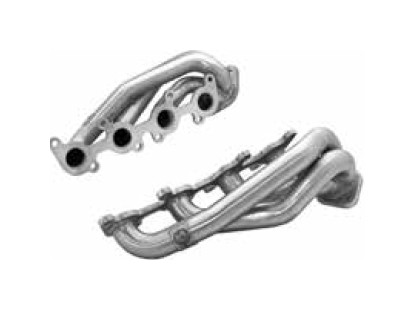
How to Install AFE 1-5/8 in. Twisted Steel Shorty Headers (11-17 5.0L) on your Ford F-150
Installation Time
4 hours
Tools Required
- 10mm, 15mm, 18mm Wrench
- 14mm 15mm, 18mm Socket
- 3/8" Ratchet
- 3/8" X 12" Extension
Shop Parts in this Guide
Parts Included:
• (x2) 10mm flange nuts
• (x2) 10mm x 1.25 x 35mm flange bolts
CAUTION: Allow time for your vehicle to cool down prior to installation. When working on or under your vehicle proceed with caution. Exhaust systems reach high temperatures and may cause serious burns. Wear protective safety equipment; eye goggles and gloves to ensure a safe installation. aFe recommends professional installation on our products. Note: aFe’s Downpipe recommends an aftermarket tuner to clear check engine light
1: (Read Instructions prior to installation). Secure vehicle on jack stands (refer to your manual for specified jack stand positions).
2: Disconnect the battery before starting work on the exhaust system.
3: Loosen the (x2) 10mm bolts on the 2 bolt exhaust flange connection.
4: Remove exhaust from all hangers and remove from truck.
5: Remove skid plate on left side of transmission cross member (4) 8mm bolts.
6: Remove (2) 6mm bolts on the Left and Right heat shields to transmission cross member.
7: Un-plug O2 sensors on Y-pipe.
8: Loosen clamp on Left converter pipe.
9: Remove (2) 10mm nuts from Left converter pipe flange to OE manifold and remove Left converter pipe.
10: Support Transmission and transfer case with floor jack and jack stand.
11: Remove (2) 12mm nuts from transmission mount.
12: Remove (4) 12mm nuts and bolts from cross member and remove cross member.
13: Remove (4) 10mm bolts on exhaust hanger mount to transmission.
14: Remove (2) 10mm nuts from right converter/Y-pipe flange to OE manifold and remove OE Y-pipe.
15: Reinstall transmission mount, and cross member temporarily.
16: Remove starter and wires (1) 6mm nut (2) 8mm nuts and (3) 8mm bolts.
17: Remove (2) 14mm nuts from right motor mount.
18: Raise right side of motor with jack.
19: Remove right heat shield on manifold (4) 6mm bolts.
20: Remove the (8) 10mm nuts from manifolds and remove manifolds.
21: Install the right side aFe power header back on the cylinder head using the original gasket and (8) 10mm nuts and tighten.
22: Reinstall (2) 14mm motor mounts nuts and tighten.
23: Reinstall starter and wires using original nuts and bolts.
24: Support left side of motor with jack.
25: Remove left side motor mount.
26: Raise left side of motor and remove heat shield on manifold (4) 6mm bolts.
27: Remove the (8) 10mm nuts from manifold and remove manifolds.
28: Install the left side header aFe power header back onto the cylinder head using the original gasket and (8) 10mm nuts and tighten.
29: Reinstall the left side motor mount bolt and tighten.
30: Support Transmission and transfer case with floor jack and jack stand.
31: Remove the cross member, and transmission mount.
32: Install factory exhaust hanger mount on Y-pipe.
33: Install Y-pipe using the (4) 10mm nuts and (4) 10mm bolts provided, make finger tight only at this time.
34: Re-install the factory exhaust hanger mount on the transmission using the original (4) 10mm bolts and tighten.
35: Re-install the cross member using the original (4) nuts and bolts and tighten.
36: Lower transmission and transfer case onto cross member and re-install the original (2) 12mm bolts on transmission mount.
37: Tighten (4) 10mm nuts, and bolts on Y-pipe to aFe power headers.
38: Plug in O2 sensor connectors and make sure they are clear of drive shaft.
39: Re-install right and left heat shields to transmission cross member using the original (2) 6mm bolts.
40: Re-install skid plate using the original (4) 8mm bolts.
41: Re-install exhaust system and fasten to aFe power Y-pipe using the (4) 7/16” nuts and bolt provided and tighten.
42: Re-connect battery.
