 FREE 1 to 3-Day Delivery on Orders $119+ Details
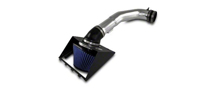
How to Install AFE Magnum Force Stage 2 Pro 5R Cold Air Intake - Polished on your F-150
Installation Time
1 hours
Tools Required
- 4mm Hex Key
- 5/16” Nut Driver
- T20 Torx Bit
- Flat-Head Screw Driver
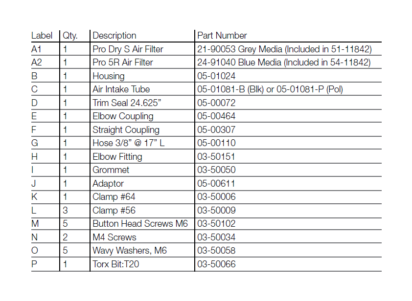
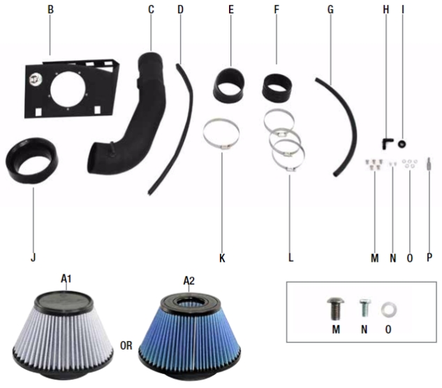
Shop Parts in this Guide
• Please read the entire instruction manual before proceeding.
• Ensure all components listed are present.
• If you are missing any of the components, call customer support at 951-493-7100.
• Ensure you have all necessary tools before proceeding.
• Do not attempt to work on your vehicle when the engine is hot.
• Disconnect the negative battery terminal before proceeding.
• Retain factory parts for future use.
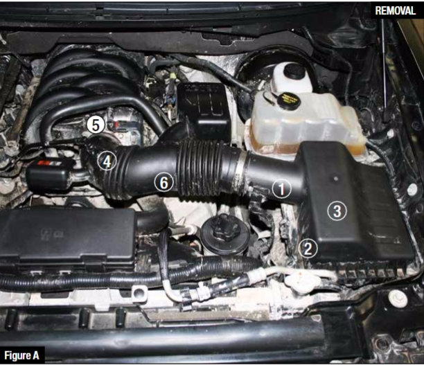
Refer to Figure A for steps 1-4
Step 1: Disconnect MAF Sensor 1 .
Step 2: Unclip the 3 clips 2 holding upper half of air box 3 .
Step 3: Disconnect and remove crankcase line 4 .
Step 4: Loosen clamp at throttle body 5 using 5/16” nut driver.
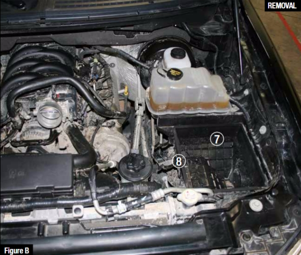
Refer to Figure A and B for steps 5-6
Step 5: Remove stock intake tube Fig A 6 , upper half of air box and air filter, not shown. Lower half of
air box 7 remains.
Step 6: Remove center clip 8 from lower half of air box.
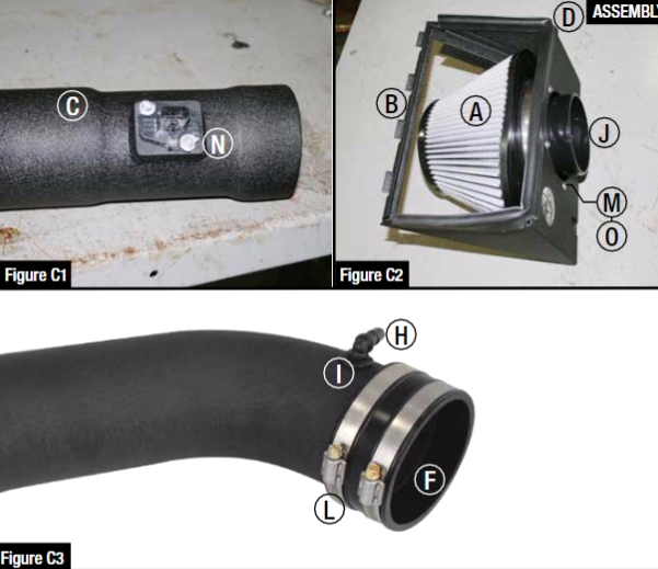
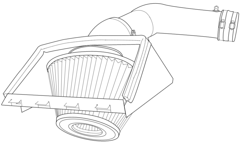
Refer to Figure C1, C2 and C3 for steps 7-12
Step 7: Refer to Fig C1: Install OE MAF sensor onto tube C using two M4 screws N .
Step 8: Refer to Fig C2: Attach filter adaptor J to housing B using five button head screws M and
five wavy washers O .
Step 9: Refer to Fig C2: Attach trim seal D to housing.
Step 10: Refer to Fig C2: Install air filter A onto adaptor and tighten clamp using 5/16” nut driver.
Step 11: Refer to Fig C3: Insert grommet I into tube and insert elbow fitting H into grommet.
Step 12: Attach straight coupling F using two #56 clamps L onto tube. (Do not tighten)
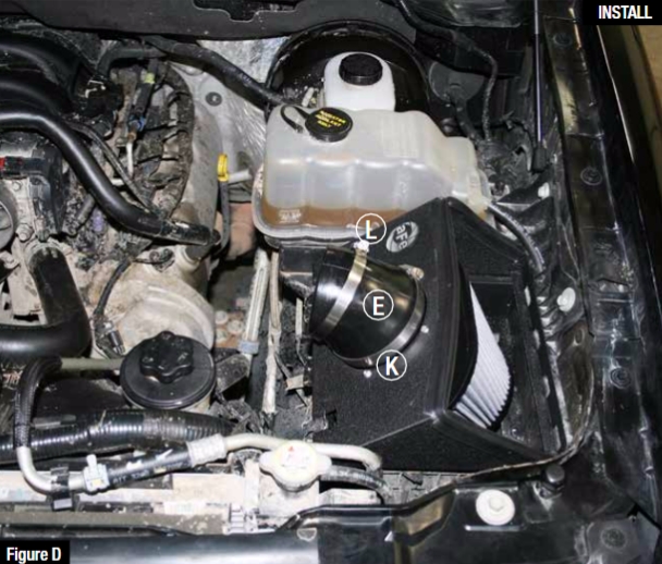
Refer to Figure D for steps 13-15
Step 13: Secure housing assembly onto lower half of stock airbox by sliding tabs into slots in stock air
box and then secure with clips.
Step 14: Attach elbow coupling E to filter adaptor using #64 clamp K . (Do not tighten)
Step 15: Position #56 clamp L onto elbow coupling. (Do not tighten)
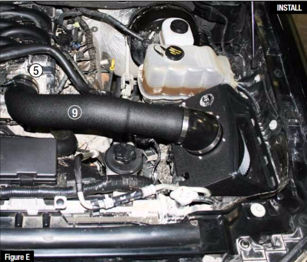
Refer to Figure E for steps 16-17
Step 16: Slide the tube assembly 9 into elbow coupling and position other end onto throttle body 5 .
Step 17: Position and tighten all clamps using 5/16” nut driver.
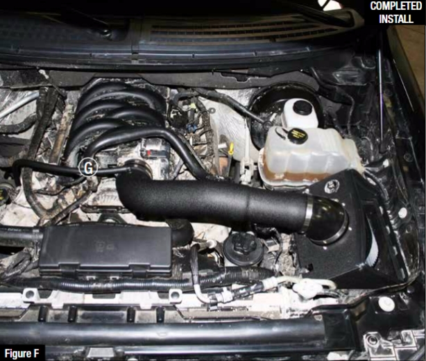
Refer to Figure F for steps 18-20
Step 18: Attach 3/8” hose G to elbow and reconnect crankcase.
Step 19: Plug in MAF harness into MAF sensor
Step 20: Reconnect negative battery terminal and be sure everything is secure and tightened.
Installation is now complete.
Step 21: Place the included CARB EO Sticker on or near the device on a smooth, clean
surface. E.O. identification label is required in passing the Smog Check Inspection.
