FREE 1 to 3-Day Delivery on Orders $119+ Details
How to Install AFE Power Magnum FORCE Stage 2 Pro Dry Cold Air Intake System on your F-150
Installation Time
1 hours
Tools Required
- 8mm socket
- 5/16” nut driver
- 10mm socket
- Flathead screwdriver
- Ratchet and extension
- T-20 Torx Bit
Shop Parts in this Guide
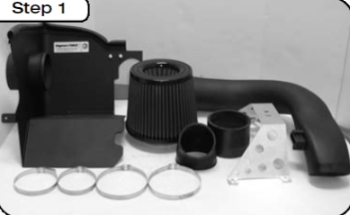
Part List:
1- Air filter p/n# 24-90008
1- Air filter Housing
1- Intake tube rotomolded
1- Intake tube support mount
1- Housing support tab
1- MAS sensor gasket
4- M6 Button head screws
5- M6 x 12 hex head screws
9- M6 washers
2- 8-32 x 5/8" screws
2- M6 Wavy washers
4- Clamps #064
2- Nylon spacers 1/8"
1- Coupler (4" x 3")
1- Coupler (3.5" x 4.0")
P.O. Box 1719 35"- Trim seal 3/4" bulb
STEP 1: Complete kit with parts.
STEP 2: Complete stock intake.
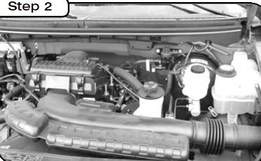
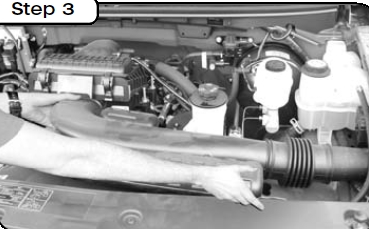
STEP 3: Disconnect negative post from battery terminal. Remove intake air duct by grabbing firmly from both sides and pulling straight back and out.
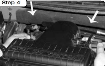
STEP 4: Disconnect the MAF sensor and breather tube on the sides of the airbox.Remove the 4 10mm screws holding the airbox to the intake manifold and remove intake box.
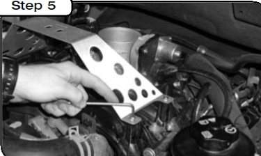
STEP 5: Install the intake tube support bracket to the intake manifold and fasten with the supplied M6 button head screws and washers.
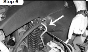
STEP 6: Remove the 8mm bolt on the top left of the fan shroud.
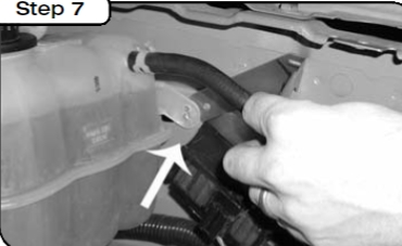
STEP 7: Remove the 8mm bolt on the side of the coolant reservoir.Sandwich the housing support bracket between the coolant reservoir tab and the fenderwell.Reinstall the 8mm bolt.
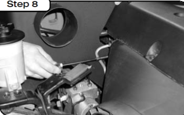
STEP 8: Position the housing into the engine bay. Line up the mounting holes with the rear support bracket and the radiator shroud and tighten all the nuts and bolts using the supplied hardware.
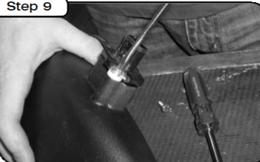
STEP 9: Transfer the MAF sensor from the factory airbox to the new intake tube .Make sure you use the provided spacer and gasket.
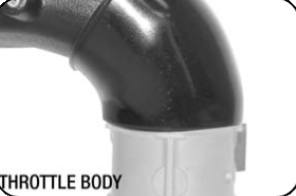
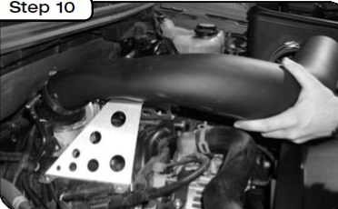
STEP 10: Place urethane coupler on the throttle body (see diagram below for correct coupler position) and the housing.Position intake duct into engine bay and tighten down the clamps.
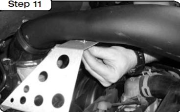
STEP 11: Line up the mounting holes on the intake duct and tighten assembly with the provided screws and washers.
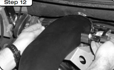
STEP 12: Re connect the MAF sensor and breather hose to the intake duct.
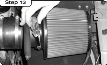
STEP 13: Install the pre-oiled filter in the housing and tighten down clamp. DO-NOT use any oil or grease. Install the housing trim seal on the sides of the panel by starting at one corner and working your way around the edge of the housing.
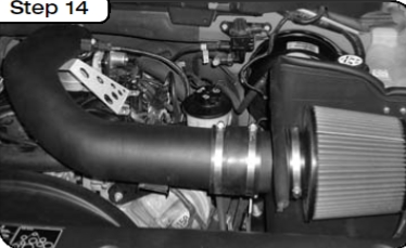
STEP 14: Place enclosed CARB EO sticker on a clean/smooth surface on or
near the intake system. EO identification label is required in passing the Smog Check inspection. Your installation is now complete. Tighten all connections and clamps. Re-check after a few hours.
STEP 15: Position coupler and clamps over throttle body (3.5" x 4.0") (clamps removed for clarification). The smaller (3.5") end of the coupler goes over the throttle body. The (4") end of the coupler goes around the intake tube.