 FREE 1 to 3-Day Delivery on Orders $119+ Details
How to Install AFE SCORCHER Module (2011 3.5L EcoBoost) on your Ford F-150
Shop Parts in this Guide
• Please read the entire instruction manual before proceeding.
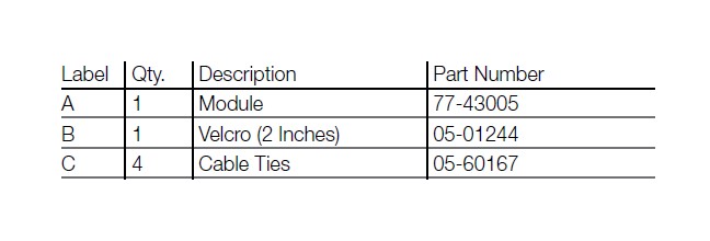
• Ensure all components listed are present.
• If you are missing any of the components, call customer support at 951-493-7100.
• Ensure you have all necessary tools before proceeding.
• Do not attempt to work on your vehicle when the engine is hot.
• Disconnect the negative battery terminal before proceeding.
• Retain factory parts for future use.
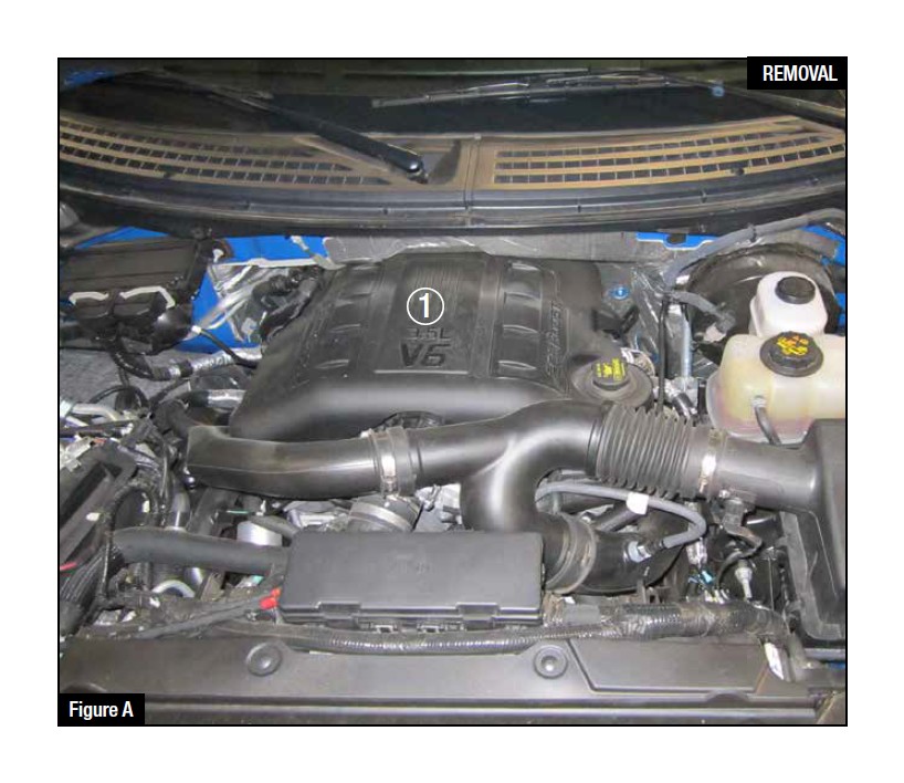
Refer to Figure A for step 1
1. Remove engine cover from vehicle 1 to gain access to your sensors.
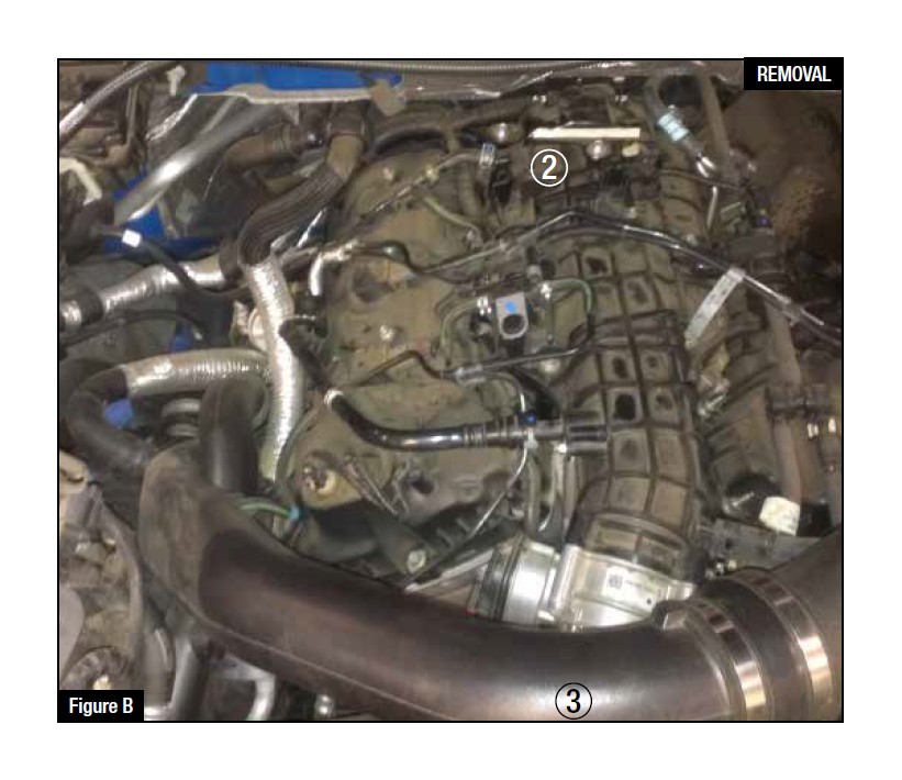
Refer to Figure B for steps 2-3
2. Locate your MAP sensor 2 . Your MAP sensor is located on the top of your intake manifold next to a set of wires.
3. Locate your TMAP sensor 3 . Your TMAP sensor is located in front of your throttle body on the charge pipe.
Notice both sensors look very similar. MAKE SURE you do not plug the jumper harness into the wrong sensor.
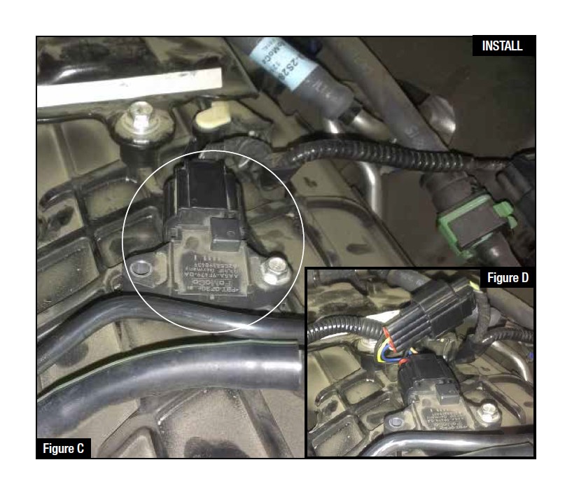
Refer to Figures C & D for steps 4-6
4. Disconnect your MAP sensor (circled in white).
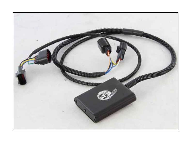
5. Locate your MAP sensor jumper harness on your aFe module. It is a wire harness with tan, black and blue colored wires.
6. Plug the female connector of the module to the male of the engine, then the male connector of the module to the female at the stock map sensor of the engine.
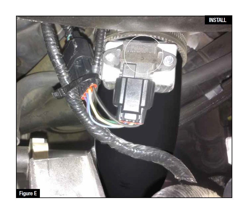
Refer to Figure E for steps 7-9
7. Disconnect your TMAP sensor (circled in white). (aFe charge-pipe shown)
8. Locate your TMAP sensor jumper harness on your aFe module. It is a wire harness with violet and green colored wires.
9. Plug the female end on the module to male end on the OE sensor, then take the male end of the module and connect to the female end on the wire loom.
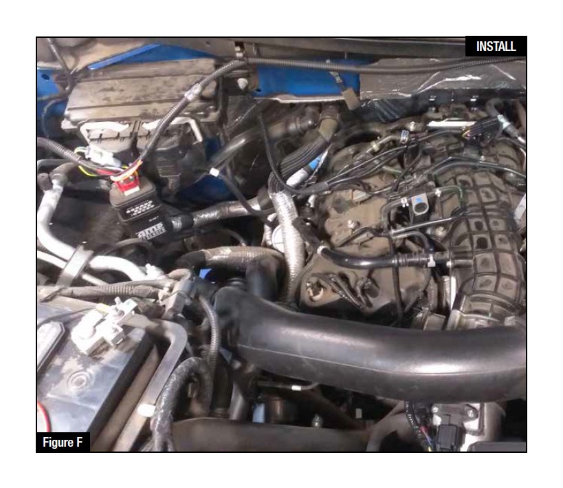
Refer to Figure F for steps 10-11
10. Route your aFe modules harness, then use the supplied cable ties to secure it.
11. Using the supplied high temp velcro, find a clean flat surface and firmly mount the module.
Note: If the sticky side of the velcro ever gets pulled off, replace it with a brand new high temp piece.
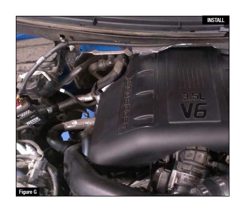
Refer to Figure F for step 12-14
12. Reinstall your engine cover.
13. The blue LED light indicates that all processes are complete and ready to go.
14. Your installation is now complete! Thank you for choosing aFe Power!
