 FREE 1 to 3-Day Delivery on Orders $119+ Details
How to Install Air Lift Ride Control System on your F-150
Tools Required
- Hoist or floor jacks
- Safety stands
- Safety glasses
- Torque wrench
- 5/16” open-end or box wrench
- 7/16” open-end or box wrench
- 9/16” open-end or box wrench
- Crescent wrench
- Ratchet with 9/16”, metric, & 1/2” deep well sockets
- Hose cutter, razor blade, or sharp knife
- Air compressor or compressed air source
- Spray bottle with dish soap/water solution
INSTALLING THE AIR SPRING KIT
Your vehicle may be equipped with a rear brake proportioning valve. Any type of load assist product could affect brake performance. We recommend that you check with your dealer before installing this type of product. If your vehicle DOES NOT have a rear brake proportioning valve or is equipped with an anti-lock type brake system, installation of a load assist product will have NO EFFECT on brake performance. UNBOLT THE LOWER BRACKET FROM THE LEAF SPRING IF THE VEHICLE IS TO BE SERVICED BY A FRAME CONTACT HOIST.
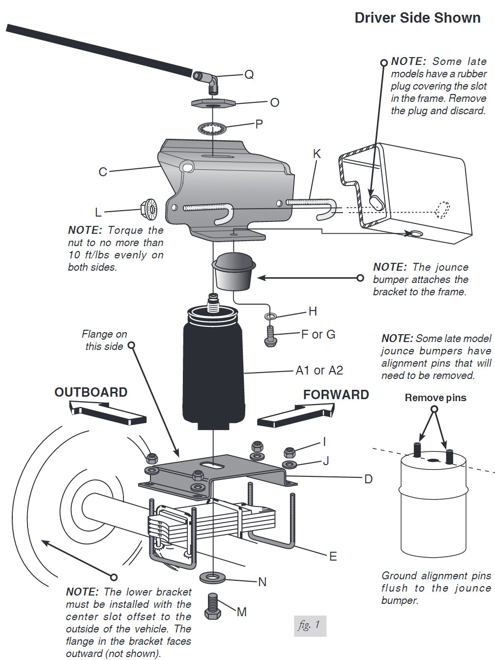
1. Remove the stock jounce bumper from under the frame (fig. 1). Some late model jounce bumpers have alignment pins that will need to be removed (fig. 1). Grind pins flush to the jounce bumper once removed.
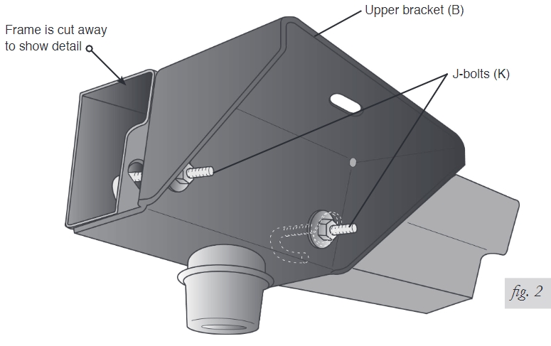
2. Insert the J-bolts (K) through the upper bracket (B or C) with the curved part facing inboard. 3. Attach the lower portion of the upper bracket (B or C) to the frame using the stock jounce bumper. Secure in place with the supplied M10-1.25 x 45 bolt (F) or M10-1.50 x 45 bolt (F) or M10-1.50 x 45 bolt
(G) and M10 lock washer (H). The upper brackets are left- and right-side specific, designated by a “L” and “R” label. 4. Insert the curved part of the J-bolts (K) into the existing slots in the frame. Be sure the J-bolts lock onto the frame securely (fig. 2). Tighten the 3/8” serrated flange nut to attach. Some late models have a rubber plug covering the slot in the frame. Remove the plug and discard.
Torque the bolts to no more than 10 ft/lbs evenly on both sides.
5. Cut the forward bolt flush to the nut.
6. Install the elbow fitting (Q) into the air port of the air sleeve. The fitting is pre-coated with thread sealant. Tighten finger tight plus two turns. Use a 7/16” open end wrench being careful to tighten on the metal hex nut only. DO NOT OVERTIGHTEN.
7. Attach the air spring (A1 or A2) to the lower bracket (D) with the 1/2” flat washer (N) and lower mounting bolt (M). Leave loose for later adjustment.
8. Set the lower bracket on the leaf spring above the axle and attach using the supplied U-bolts (E), 3/8” flat washers (J), and 3/8” nyloc nuts (I) (fig. 1).
9. Guide the threaded post of the air fitting through the slot in the upper bracket.
10.Install the 3/4” nylon nut (O) and lock washer (P) on to the upper threaded post of the air spring. Leave loose for final adjustment.
INSTALLING THE AIR LINES
1. Choose a convenient location for mounting the inflation valves. Popular locations for the inflation valve are: a. The wheel well flanges. b. License plate recess in bumper. c. Under the gas cap access door. d. Through license plate itself. What ever the chosen location is, make sure there is enough clearance around the inflation valves for an air chuck.
2. Drill a 5/16” hole to install the inflation valves.
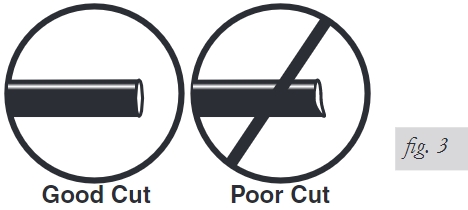
3. Cut the air line assembly (AA) in two equal lengths. WHEN CUTTING OR TRIMMING THE AIR LINE, USE A HOSE CUTTER, A RAZOR BLADE OR A SHARP KNIFE. A CLEAN, SQUARE CUT WILL ENSURE AGAINST LEAKS. DO NOT USE WIRE CUTTERS OR SCISSORS TO CUT THE AIR LINE. THESE TOOLS MAY FLATTEN OR CRIMP THE AIR LINE, CAUSING IT TO LEAK AROUND THE O-RING SEAL INSIDE THE ELBOW FITTING (FIG. 3)
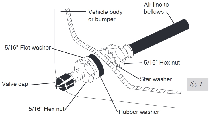
4. Place a 5/16” nut (GG) and a star washer (FF) on the air valve. Leave enough of the inflation valve in front of the nut to extend through the hole and have room for the rubber washer (EE), flat washer (DD), and 5/16” nut (GG) and cap (CC). There should be enough valve exposed after installation - approximately 1/2” - to easily apply a pressure gauge or an air chuck (fig. 4).
5. Push the inflation valve through the hole and use the rubber washer (EE), flat washer (DD), and another 5/16” nut (GG). Tighten the nuts to secure the assembly in place (fig. 4)
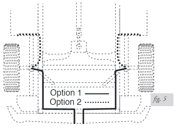
6. Route the air line along the frame to the air fitting on the air spring (fig. 5). Keep AT LEAST 6” of clearance between the air line and heat sources, such as the exhaust pipes, muffler, or catalytic converter. Avoid sharp bends and edges. Use the plastic tie straps (BB) to secure the air line to fixed, non-moving points along the chassis. Be sure that the tie straps are tight, but do not pinch the air line. Leave at least 2” of slack to allow for any movement that might pull on the air line
7. Cut off air line leaving approximately 12” of extra air line. A clean square cut will ensure against leaks (see fig. 3). Insert the air line into the air fitting. This is a push to connect fitting. Simply push the air line into the 90° swivel fitting until it bottoms out (9/16” of air line should be in the fitting).
8. IMPORTANT: With the top and bottom still loose, inflate the air springs to approximately 10 PSI. Use the slots in the brackets to correctly align the air spring between the upper and lower brackets. this can be accomplished by tapping it inboard or outboard for proper alignment. There should be a symmetrical cushion of air around the base of the air spring when correctly positioned.
CHECKING FOR LEAKS
1. Inflate the air spring to 30 PSI and spray all connections and the inflation valves with a solution of 1/5 liquid dish soap and 4/5 water to check for leaks. Spot leaks easily by looking for bubbles in the soapy water.
2. After the test, deflate the springs to the minimum pressure required to restore the normal ride height, no less than 5 PSI.
3. Check the air pressure again after 24 hours. A 2-4 PSI loss after initial installation is normal. Retest for leaks if the loss is more than 5 lbs.
FIXING LEAKS
1. If there is a problem with the swivel fitting:
a. Check the air line connection by deflating the spring and removing the line by pulling the collar against the fitting and pulling firmly on the air line. Trim 1” off the end of the air line. Be sure the cut is clean and square (see fig. 12). Reinsert the air line into the push-to-connect fitting.
b. Check the threaded connection by tightening the swivel fitting another ½ turn. If it still leaks, deflate the air spring, remove the fitting, and re-coat the threads with thread sealant. Reinstall by hand tightening as much as possible, then use a wrench for an additional two turns.
2. If there is a problem with the inflation valve, then:
a. Check the valve core by tightening it with a valve core tool.
b. Check the air line connection by removing the air line from the barbed type fitting. DO NOT CUT THE AIR LINE COMPLETELY OFF AS THIS WILL NICK THE BARB AND RENDER THE FITTING USELESS.
3. If the preceding steps have not resolved the problem, call Air Lift customer service at (800) 248-0892 for assistance.
