 FREE 1 to 3-Day Delivery on Orders $119+ Details
How to Install an Air Lift Ride Control System on your Ford F-150
INSTALLATION GUIDE
Installation Diagram
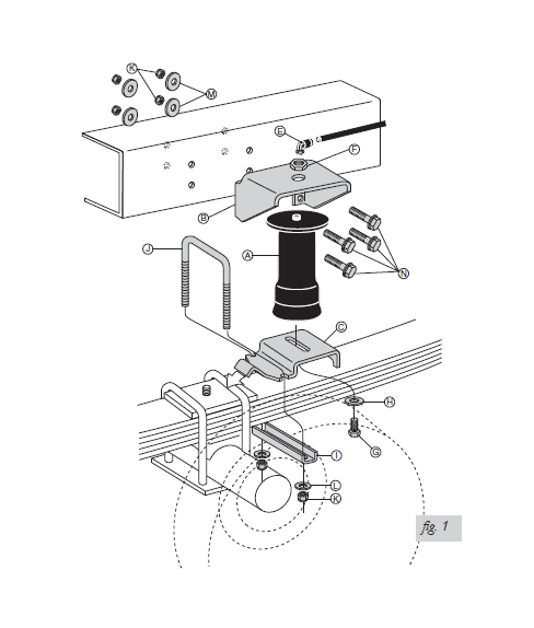
FIFTH WHEEL HITCH
If you have a 1997-2002 Ford F-150, short box, extended cab with a Reese style 5th wheel hitch kit installed, use Air Lift kit #59542 instead of this kit or contact Air Lift customer service at (800) 248-0892 for the correct brackets. Ask for bracket kit #26270.
Your vehicle may be equipped with a rear brake proportioning valve. Any type of load assist product could affect brake performance. Air Lift recommends checking with your dealer before installing this type of product. If the vehicle DOES NOT have a rear brake proportioning valve or is equipped with an anti-lock type brake system, installation of a load assist product WILL NOT have an effect on the brake system performance.
RIDE HEIGHT AND CLEARANCE DISTANCE
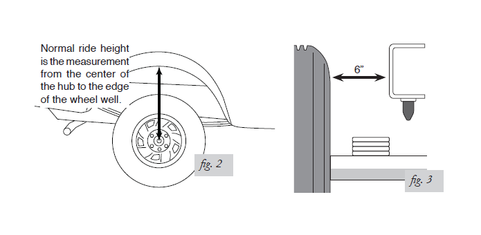
1. Determine the normal ride height. The normal ride height is the distance between the bottom edge of the wheel-well and the center of the hub. In some cases, the normal ride height is not perfectly level.
a. Remove unusual loads and examine your vehicle from the side to ensure it is on a level surface.
b. If necessary, use a jack to raise the rear end so that the vehicle achieves the original “as delivered” ride height.
2. Measure the distance between the center of the hub and the bottom edge of the wheel well (fig. 2). This is normal ride height. Record the measurement below:
Normal ride height: _____________ inches
3. Measure the distance between the frame and the tire. This kit requires a MINIMUM of 6” of clearance for a FULLY INFLATED air spring (fig. 3).
RAISING THE VEHICLE
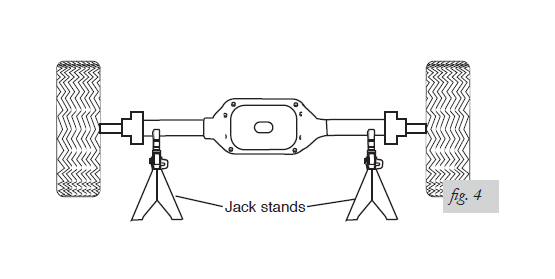
1. Raise the vehicle with a hoist or jack stands and remove the wheels (fig. 4).
2. Check the distance between the center of the hub and the bottom edge of the wheel well to ensure that it is at the normal ride height recorded above. If not, raise the frame or lower the axle as necessary to restore the original distance.
a. If the vehicle is raised with an axle contact hoist, place axle stands under the frame
and lower the axle as needed.
b. If the vehicle is raised with a frame contact hoist, place axle stands under the axle
and lower the frame as needed.
c. If the vehicle is raised with a jack and supported with axle stands on the frame, use
a floor jack to lower the axle.
ASSEMBLING THE INSTALLATION TOOL
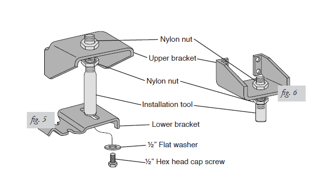
1. The tool provided with this kit will assist in proper setup and alignment of the air spring and will also position the upper bracket for drilling the bolt holes. The tool attaches to the upper and lower brackets and is rigid so that it will self-align the upper bracket. The threaded section of the upper part of the tool ensures that the air spring can only be mounted at the correct height. The air spring will work throughout the entire threaded range on the tool. Correct placement depends on the particular vehicle application.
2. Secure the upper bracket (B) to the installation tool (D) using the provided nylon nut (F) (fig. 5).
1987 and older Chevy/GMC 4WD only: The upper bracket must be installed with the legs of the upper bracket “legs up”. Refer to fig. 6.
3. Loosely attach the tool to the lower bracket (C) using 1/2” flat washer (H) and 1/2” bolt (G). Refer to fig. 5. Leave loose for adjustment
Installing the RideControl System
IMPORTANT: There are special application instructions for each vehicle make. The placement and installation of the kit depends on the type of vehicle and varies depending on the location of brake lines, gas lines, hydraulic lines, and any other items that may interfere with drilling and mounting. The installation tool included will aide in checking for obstacles and clearance issues.
The kit can be installed in front or behind the axle, even staggered on opposite sides as long as the sufficient mounting envelope is available. Some situations, such as vehicles with staggered shock absorbers, may require installing the air springs in front and behind the axle on opposite sides of the vehicle.
The following instructions have been divided by vehicle manufacturer. Please use the correct instructions for your vehicle.
DODGE VEHICLES
1994 – Current Dodge 4WD Pickups:
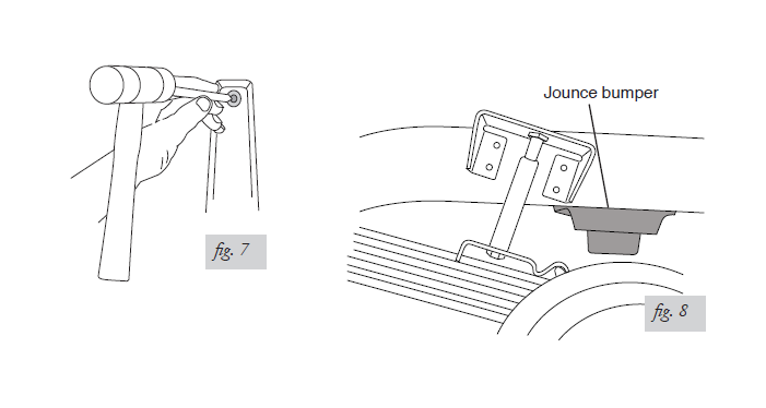
1. If so equipped, it will be necessary to remove the inner fenderwell liner. Carefully drive the pin through the fasteners with a center punch (fig. 7). These fasteners will be reused along with a special spacer to reattach the liner and provide clearance for the air spring. See page # for reinstallation instructions. Do not reinstall until after the entire system has been leak and clearance tested.
2. Please proceed to “Positioning the Upper Bracket” on page 7.
1993 and Older Dodge 4WD Pickups:
1. It may be necessary to remove or trim the rubber jounce bumper bracket in order to provide sufficient clearance for the fully inflated air spring (fig. 8).
2. Please proceed to “Positioning the Upper Bracket” on page 7.
CHEVROLET/GMC VEHICLES
1987 and Older Chevrolet/GMC 4WD Pickups:
1. It may be necessary to remove or trim the rubber jounce bumper bracket in order to
provide sufficient clearance for the fully inflated air spring (fig. 8).
2. The air spring kit will mount staggered and the upper bracket will be attached with the
legs facing upward.
3. Please proceed to “Positioning the Upper Bracket” on page 7.
1988 – 1998 Chevrolet/GMC:
1. On the driver-side, forward of the axle, the threaded end of the bolt that holds the brake line clip on the inside of the frame protrudes through to the outside of the frame rail where the upper bracket will be attached to the frame. The bolt will prevent the upper bracket from laying flush to the frame rail. It will be necessary to remove this bolt. There are other clips to sufficiently hold the lines to the frame.
2. The air spring kit mounts forward of the axle.
3. Please proceed to “Positioning the Upper Bracket” on page 7.
1999 – 2007 Silverado/Sierra (GMT 800):
1. The air spring kit will mount forward of the axle.
2. Please proceed to “Positioning the Upper Bracket” on page 7.
FORD VEHICLES
1997 – 2004 Ford F-150 2WD & 4WD Trucks:
1. This kit mounts forward of the rear axle. It is necessary to relocate the bolt holding the brake line bracket to the inside of the frame rail on the driver-side.
NOTE: The special edition Harley Davidson models have a spring retaining strap forward of the axle. This has to be removed in order to install this product.
a. Remove the nut from the outside of the frame rail. Pull the brake line bracket away
from the inside of the frame rail.
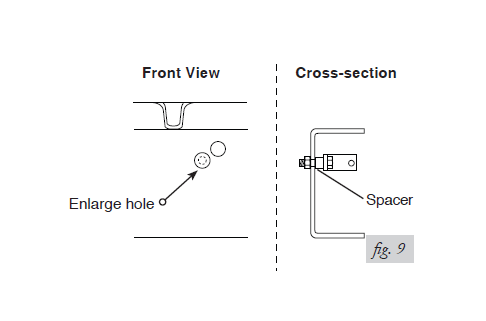
b. Enlarge the hole just below and slightly forward of the existing attachment. Use a
3/8” drill bit to enlarge the hole (fig. 7, front view).
c. Place the provided spacer (P) on the bracket side of the threads and then reattach
the brake line bracket using the original nut (fig. 7, cross-section). This will not
compromise the brake line in any way.
2. Please proceed to “Positioning the Upper Bracket” below.
POSITIONING THE UPPER BRACKET
1. Using the slot in the lower bracket, push the upper bracket against the frame rail.
2. Use the nylon and pal nut on the threaded portion of the tool to adjust the upper bracket so that the legs are flat against the frame rail and all four holes are in the middle section of the frame rail. The mounting holes must not fall on the rounded edges of the frame rail and at least 1.5” must be left above the top of the upper bracket for air fitting clearance.
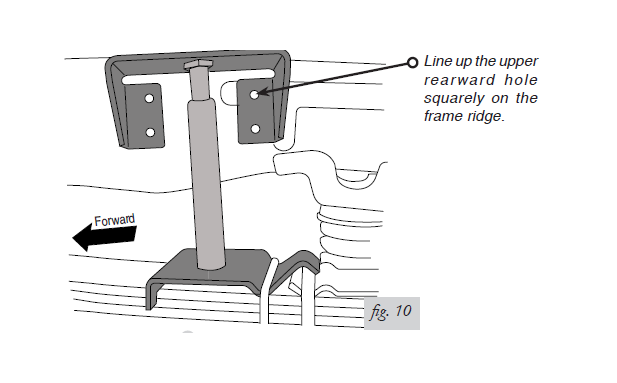
a. ‘99 Silverado/Sierra: Adjust the upper bracket on the threaded tool until the upper rearward hole lines up squarely on the frame ridge (fig. 10). Not all ‘99 Silverado/ Sierra models have this reinforcing frame ridge. If the vehicle does not have it, place the bracket in the middle section of the frame.
b. Dodge and Ford Pickups: Many Dodge and Ford pickup chassis have an indent in the frame rail. It is necessary to use the provided spacers behind the mounting holes in such instances.
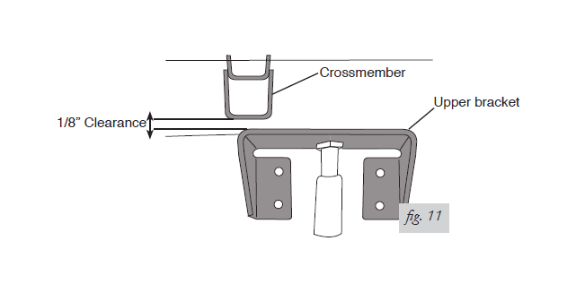
c. 2000 Dodge 1500: There must be 1/8” of clearance from the upper bracket to the bed crossmember when mounting the upper bracket to the frame (fig. 11).
ATTACHING THE LOWER BRACKET
1. Set the assembly on the leaf spring, forward or behind the axle depending upon
application.
NOTE: With ‘99 Silverado and Sierra, if the tool hits the fender flange, drop the axle until the unit clears the flange.
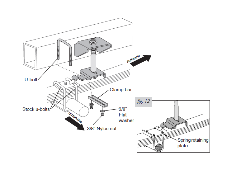
2. With the hook end of the lower bracket placed over the stock U-bolt (fig. 12) or edge of the spring retaining plate (fig. 12, inset), secure the lower bracket to the leaf spring with the provided U-bolt (J), clamp bar (I), 3/8” flat washers (L), and 3/8” nyloc nuts (K). Torque to 16 ft/lbs.
NOTE: The bracket will pull down flat to the leaf spring when the lock nuts are tightened.
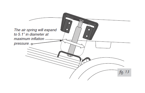
3. The air spring will expand to 5.1” in diameter at maximum inflation pressure. Check horizontally along the shaft of the installation tool for sufficient clearance of 2.50” around the tool (fig. 13). Be sure to check and adjust any fasteners coming through the frame from the inboard side.
ATTACHING THE UPPER BRACKET
CAUTION: BEFORE DRILLING, CHECK THE BACK SIDE OF THE FRAME FOR CLEARANCE ISSUES SUCH AS, BRAKE LINES, GAS LINES, ELECTRICAL LINES, ETC. ANY OBSTACLES WILL NEED TO BE TEMPORARILY RELOCATED TO CLEAR THE AREA.
1. Center punch the lower rear hole and drill a 3/8” hole.
2. Loosely install a washer head frame bolt (N), large flat washer (M), and nyloc nut (K).
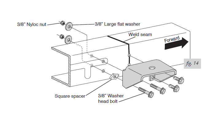
a. ‘99 – 2007 Silverado/Sierra (GMT 800): Insert the square spacer (O) between the upper bracket and frame rail (fig. 14). Loosely attach with 3/8” washer head bolts (N), 3/8” large flat washers (M), and 3/8” nyloc nuts (K).
b. 2000 and later Dodge 1500: Use small O.D. washer behind the frame on the rear bottom mounting bolt.
c. Dodge and early Ford pickups: Many Dodge and Ford pickup chassis have an indent in the frame rail. Use spacers provided behind the mounting holes in the upper bracket that fall into this indented area. Use two round spacers (P) for Dodge vehicles and one square spacer (O) for Ford vehicles per side.
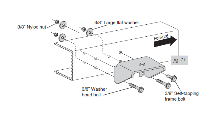
d. Late model Ford F-150: Some models have a shock reinforcement on the passenger side that boxes in the frame. The forward holes will fall behind this boxed in section. The washer head bolts (N), 3/8” large flat washers (M), and 3/8” nyloc nuts (K) can still be used in all mounting hole locations, however, it will be easier to use a 3/8” self-tapping frame bolt (Q) in the forward upper hole location (fig. 15).
3. Center punch the forward lower hole.
a. Drill a 5/16” hole for ‘99 and newer Silverado/Sierra and late model Ford F-150 if using
a self-tapper (per step 2d, 7a, 5).
NOTE: The forward holes will be on the welded section of the frame.
b. Drill a 3/8” hole for all other installs.
c. Dodge Dakota: The forward bottom hole will have to be drilled through the jounce
bumper bracket and the frame. A spacer (P) is provided for the upper forward hole
to compensate for the thickness of the jounce bumper bracket.
4. Remove the tool by removing the bolt securing the tool to the lower bracket. Swing the bracket up and remove the nylon nut on the top of the upper bracket. Remove the tool. Save the removed hardware, as it will be reused to mount the air spring.
5. Replace the upper bracket to the mounting location and secure at the forward, lower
mounting hole using washer head frame bolt (N), large flat washer (M), and nyloc nut
(K) as shown fig. 1, except in ‘99 Silverado/Sierra (fig. 14) or late model Ford F-150 (per
fig. 15) use a self-tapping frame bolt (Q). Tighten securely.
a. Dodge and Early Ford pickups: Use provided spacers if the mounting hole falls in
the indent in the frame rail.
6. Center punch and drill the remaining two holes. Drill a 5/16” hole for the forward upper
hole on the ‘99 Silverado/Sierra only, otherwise, drill 3/8” holes for all mounting holes.
7. Install correct mounting hardware in each upper mounting hole location. See below for
vehicle specific instructions:
a. ‘99 Silverado/Sierra and late model Ford F-150: Install a self-tapper (Q) in the
forward upper hole and tighten securely. In the rear upper hole, install a washer head
frame bolt (N), large flat washer (M), and nyloc nut (K). Torque to 20 ft/lbs.
b. Dodge Dakota: In the forward upper hole, install a spacer (P) behind the upper
bracket. In both forward and rearward holes, install washer head frame bolt (N),
large flat washer (M), and nyloc nut (K). Torque to 20 ft/lbs.
c. Dodge and early Ford pickups: Use provided spacers if the mounting hole falls in
the indent in frame rail.
d. All other vehicles: Install washer head frame bolt (N), large flat washer (M), and nyloc nut (K) in both mounting holes. Torque to 20 ft/lbs.
INSTALLING THE AIR SPRING
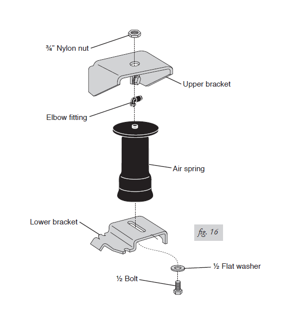
1. Install 90 degree air swivel fitting (E) to the top of the air spring (A) (fig. 16). Use a 7/16” open end wrench being careful to tighten on the metal hex nut only. Tighten 1 and 1/2 turns. Do not over tighten.
NOTE: This fitting is pre-coated with sealant.
2. Guide the fitting through the center mounting hole in the upper bracket (fig. 16).
3. Attach the air spring to the lower bracket using ½” flat washer (H) and ½” bolt (G).
Carefully hand turn the air spring onto the lower mounting bolt. Leave loose for later
adjustment.
4. Loosely, install nylon nut (F) over the air fitting and onto the upper thread post of the air spring (fig. 16).
INSTALLING THE AIR LINES
1. Choose a convenient location for mounting the inflation valves. Popular locations for the inflation valve are:
a. The wheel well flanges
b. The license plate recess in bumper
c. Under the gas cap access door
d. Through the license plate
NOTE: What ever the chosen location is, make sure there is enough clearance around the inflation valves for an air chuck.
2. Drill two 5/16” holes to install the inflation valves.
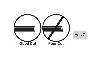
3. Cut the air line assembly in two equal lengths.
CAUTION: WHEN CUTTING OR TRIMMING THE AIR LINE, USE A HOSE CUTTER, A RAZOR BLADE, OR A SHARP KNIFE. A CLEAN, SQUARE CUT WILL ENSURE AGAINST LEAKS. DO NOT USE WIRE CUTTERS OR SCISSORS TO CUT THE AIR LINE. THESE TOOLS MAY FLATTEN OR CRIMP THE AIR LINE CAUSING IT TO LEAK AROUND THE O-RING SEAL INSIDE THE ELBOW FITTING (FIG. 17).
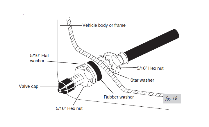
4. Place a 5/16” nut and star washer on the air valve. Leave enough of the inflation valve in front of the nut to extend through the hole and have room for the rubber washer, flat washer, and 5/16” nut and cap. There should be enough valve exposed after installation— approximately ½”— to easily apply a pressure gauge or an air chuck (fig. 18).
5. Push the inflation valve through the hole and use the rubber washer, flat washer, and another 5/16” nut to secure it in place. Tighten the nuts to secure the assembly (fig. 18).
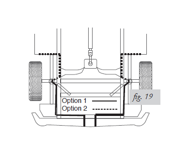
6. Route the air line along the frame to the air fitting on the air spring (fig. 19). Keep AT LEAST 6” of clearance between the air line and heat sources, such as the exhaust pipes, muffler, or catalytic converter. Avoid sharp bends and edges. Use the plastic tie straps to secure the air line to fixed, non-moving points along the chassis. Be sure that the tie straps are tight, but do not pinch the air line. Leave at least 2” of slack to allow for any movement that might pull on the air line.
7. Cut off the air line, leaving approximately 12” of extra air line. A clean square cut will ensure against leaks (see fig. 17). Insert the air line into the air fitting. This is a pushto- connect fitting. Simply push the air line into the 90° swivel fitting until it bottoms out (9/16” of air line should be in the fitting).
8. Repeat the installation procedure for the remaining side of the vehicle. Inflate the sleeves to 10 psi and adjust the sleeve in the lower bracket slot so the sleeve is perpendicular to the mounting brackets. Tighten the ½” bottom bolt securely. Reinstall tires.
ALIGNING THE AIR SPRING
1. IMPORTANT: With the bottom and top of the air spring still loose, inflate the air spring to approximately 10 p.s.i.
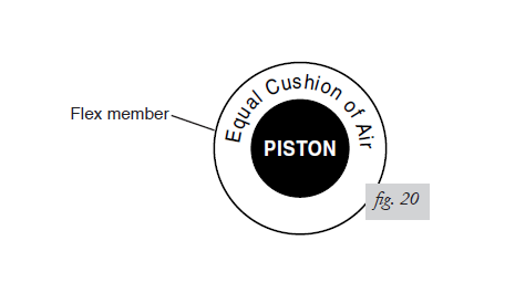
2. Use the slotted adjustment in the lower bracket to correctly align the air spring between the upper and lower brackets. This can be accomplished by lightly tapping it inboard or outboard for proper alignment. There should be a symmetrical cushion of air around the base of the air spring when correctly positioned (fig. 20).
3. Tighten the lower mounting bolt with a ¾” wrench. Hand tight is sufficient. Do not attempt to hold the air spring with any type of tool.
4. Tighten the nylon nut to 4 ft/lbs.
5. On the driver side, it may be necessary to secure the emergency brake cable away from the air spring using straps (BB) to prevent rubbing. Tie both cables together where they cross each other
6. Repeat entire installation procedure for the other side of the vehicle.
CHECKING FOR LEAKS
1. Inflate the air spring to 30 p.s.i.
2. Spray all connections and the inflation valves with a solution of 1/5 liquid dish soap and 4/5 water to check for leaks. You should be able to spot leaks easily by looking for bubbles in the soapy water.
3. After the test, deflate the springs to the minimum pressure required to restore the normal ride height, no less than 10 p.s.i.
4. IMPORTANT: Check the air pressure again after 24 hours. A 2 – 4 p.s.i. loss after initial installation is normal. Retest for leaks if the loss is more than 5 p.s.i.
FIXING LEAKS
1. If there is a problem with the swivel fitting,
a. Check the air line connection by deflating the spring and removing the line by pulling the collar against the fitting and pulling firmly on the air line. Trim 1” off the end of the air line. Be sure the cut is clean and square. Reinsert the air line into the pushto- connect fitting.
b. Check the threaded connection by tightening the swivel fitting another 1/2 turn. If it still leaks, deflate the air spring, remove the fitting, and re-coat the threads with thread sealant. Reinstall by hand tightening as much as possible, then use a wrench for an additional two turns.
2. If there is a problem with the inflation valve,
a. Check the valve core by tightening it with a valve core tool.
b. Check the air line connection by removing the air line from the barbed type fitting.
CAUTION: DO NOT CUT IT OFF, AS THIS WILL USUALLY NICK THE BARB AND RENDER THE FITTING USELESS. CUT AIR LINE OFF A FEW INCHES IN FRONT OF THE FITTING AND USE A PAIR OF PLIERS OR VICE-GRIPS TO PULL/TWIST THE AIR LINE OFF THE FITTING.
3. If the preceding steps have not resolved the problem, call Air Lift customer service at (800) 248-0892 for assistance.
REINSTALLING THE FENDERWELL LINER
(Late model 4WD Dodge only)
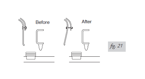
1. Reinstall the inner fenderwell liner using the original fasteners and provided spacers to allow for air spring clearance (fig. 21).
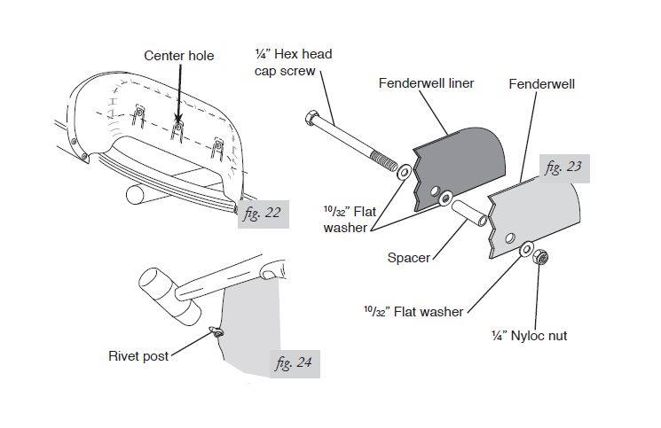
2. Place the spacer (S) between the fenderwell liner and the fenderwell at the center hole (fig. 22) in the fenderwell liner (the hole nearest the air spring). Attach using the ¼” hex head cap screw (R), the 10/32” flat washers (T), and ¼” nyloc nut (U) (fig. 23).
NOTE: Fasten the hex head cap screw with the washer and nut behind the fenderwell. Tighten securely.
3. Replace the remaining fenderwell liner rivets carefully. Push the rivets through the fenderwell liner by hand. They should push through completely.
4. From the opposite side, use a rubber mallet and carefully tap the rivet posts back into the rivets in order to secure them properly (fig. 24). Repeat this process for all remaining rivets.
Before Operating
INSTALLATION CHECKLIST (To be completed by installer)
Clearance test — Inflate the air springs to 60 p.s.i. and ensure there is at least ½”
clearance around each sleeve, away from anything that might rub against them. Be sure
to check the tire, brake drum, frame, shock absorbers and brake cables.
Leak test before road test — Inflate the air springs to 30 p.s.i., check all connections for leaks with a soapy water solution. See page # for tips on how to spot leaks. All leaks must be eliminated before the vehicle is road tested.
Heat test — Be sure there is sufficient clearance from any heat sources — at least 6”
for air springs and air lines. If a heat shield was included in the kit, install it. If there is no heat shield, but one is required, call (800) 248-0892.
Fastener test — Recheck all bolts for proper torque.
Road test — The vehicle should be road tested after the preceding tests. Inflate the
air springs to 25 p.s.i. (50 p.s.i. if the vehicle is loaded). Drive the vehicle 10 miles and
recheck for clearance, loose fasteners and air leaks.
Operating instructions — If professionally installed, the installer should review the
operating instructions on page 16 with the owner. Be sure to provide the owner with all
of the paperwork which came with the kit.
Technician’s Signature ________________________
Date ______________
POST-INSTALLATION CHECKLIST (To be completed by owner)
Overnight leakdown test — Recheck air pressure after 24 hours. If pressure has dropped more than 5 p.s.i., check for leaks and fix accordingly following the instructions on page 13 or return to the installer for service.
Air pressure requirements — The air pressure requirements are detailed on page #.
Regardless of the load, the air pressure should always be adjusted so that normal ride
height is maintained at all times.
30 day or 500 mile test — The air spring system must be rechecked after 30 days or 500 miles, whichever comes first. If any part shows signs of rubbing or abrasion, the source should be identified and moved, if possible. If it is not possible to relocate the cause of the abrasion, the air spring may need to be remounted. If professionally installed, the installer should be consulted. Check all fasteners for tightness.
Troubleshooting Guide
Problems maintaining air pressure, without on-board compressor.
1. Leak test the air line connections and threaded connection of the elbow into the air spring. See “Fixing Leaks” to repair.
2. Leak test the inflation valve for leaks at the air line connection or dirt or debris in the
valve core. See “Fixing Leaks” to repair.
3. Inspect the air line to be sure it is not pinched. Replace leaking components.
4. Inspect air line for holes and cracks. Replace as needed.
5. A kink or fold in the air line. Reroute as needed.
6. At this point the problem is most likely a failed air spring - either a factory defect or an operating problem. Please call Air Lift at (800) 248-0892 for assistance or a replacement air spring.
Maintenance and Servicing
By following these steps, vehicle owners will obtain the longest life and best results from their air springs.
1. Inflate your air springs to 60 p.s.i. before adding the payload. After the vehicle is loaded, adjust your air pressure to level the vehicle and for ride comfort.
2. Check the air pressure weekly.
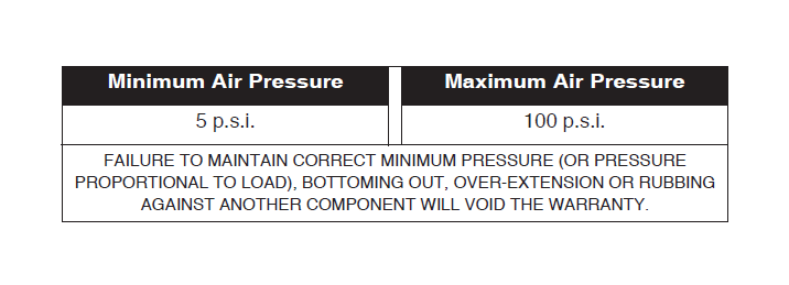
3. Always maintain normal ride height. Never inflate beyond 100 p.s.i.
4. If you develop an air leak in the system, use a soapy water solution of 1/5 liquid dish
soap and 4/5 water. to check all air line connections and the inflation valve core before
deflating and removing the air spring.
5. When increasing load, always adjust the air pressure to maintain the normal ride height. Increase or decrease pressure from the system as necessary to attain normal ride height for optimal ride and handling. Remember that loads carried behind the axle (including tongue loads) require more leveling force (pressure) than those carried directly over the axle.
CAUTION: FOR YOUR SAFETY AND TO PREVENT POSSIBLE DAMAGE TO YOUR VEHICLE, DO NOT EXCEED MAXIMUM GROSS VEHICLE WEIGHT RATING (GVWR), AS INDICATED BY THE VEHICLE MANUFACTURER. ALTHOUGH YOUR AIR SPRINGS ARE RATED AT A MAXIMUM INFLATION PRESSURE OF 100 P.S.I. THE AIR PRESSURE ACTUALLY NEEDED IS DEPENDANT ON YOUR LOAD AND GVWR, WHICH MAY BE LESS THAN 100 P.S.I. CHECK YOUR VEHICLE OWNERS MANUAL AND DO NOT EXCEED THE MAXIMUM LOAD LISTED FOR YOUR VEHICLE.
6. Always add air to springs in small quantities, checking the pressure frequently. Sleeves require less air volume than a tire and inflate quickly.
7. Should it become necessary to raise the vehicle by the frame, make sure the system is at minimum pressure (5 p.s.i.) to reduce the tension on the suspension/brake components. Use of on board leveling systems do not require deflation or disconnection.
Warranty and Returns Policy
Air Lift Company warrants its products, for the time periods listed below, to the original retail purchaser against manufacturing defects when used on catalog-listed applications on cars, vans, light trucks and motorhomes under normal operating conditions for as long as Air Lift manufactures the product. The warranty does not apply to products that have been improperly applied, improperly installed, used in racing or off-road applications, used for commercial purposes, or which have not been maintained in accordance with installation instructions furnished with all products. The consumer will be responsible for removing (labor charges) the defective product from the vehicle and returning it, transportation costs prepaid, to the dealer from which it was purchased or to Air Lift Company for verification. Air Lift will repair or replace, at its option, defective products or components. A minimum $10.00 shipping and handling charge will apply to all warranty claims. Before returning any defective product, you must call Air Lift at (800) 248-0892 in the U.S. and Canada (elsewhere, (517) 322-2144) for a Returned Materials Authorization (RMA) number. Returns to Air Lift can be sent to: Air Lift Company • 2727 Snow Road • Lansing, MI • 48917.
Product failures resulting from abnormal use or misuse are excluded from this warranty. The loss of use of the product, loss of time, inconvenience, commercial loss or consequential damages is not covered. The consumer is responsible for installation/reinstallation (labor charges) of the product. Air Lift Company reserves the right to change the design of any product without assuming any obligation to modify any product previously manufactured.
This warranty gives you specific legal rights and you may also have other rights that vary from state-to-state. Some states do not allow limitations on how long an implied warranty lasts or allow the exclusion or limitation of incidental or consequential damages. The above limitation or exclusion may not apply to you. There are no warranties, expressed or implied including any implied warranties of merchantability and fitness, which extend beyond this warranty period. There are no warranties that extend beyond the description on the face hereof. Seller disclaims the implied warranty of merchantability. (Dated proof of purchase required.)
