FREE 1 to 3-Day Delivery on Orders $119+ Details
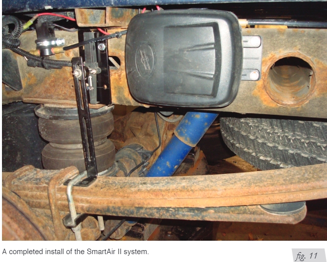
How to Install Air Lift SmartAIR II Automatic Leveling System - Single Path on your F-150
Installing the SmartAir II System
RECOMMENDED COMPRESSOR LOCATIONS Important LOCATE COMPRESSOR IN DRY, PROTECTED AREA ON VEHICLE. DIRECT SPLASH OR EXCESSIVE MOISTURE CAN DAMAGE THE COMPRESSOR AND CAUSE SYSTEM FAILURE. Disclaimer: If choosing to mount the compressor outside the vehicle, keep in mind the compressor body must be shielded from direct splash. Please also remember ... • To avoid mounting the compressor or Electronic Height Sensor (EHS) in high-heat environments such as near exhaust or under hood. • To check to make sure the harness will reach all required components based on where they will be mounted. • The compressor can be mounted in any position — vertical, upside down, sideways, etc.
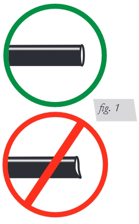
INSTALLING THE COMPRESSOR AND EXHAUST SOLENOID 1. If mounting the compressor outside the cabin, select a rigid mounting location on the vehicle’s frame or crossmember that shields the compressor from the elements and heat sources. 2. Once a location has been determined, use self-tapping screws supplied with compressor to fasten compressor securely to the vehicle. Make sure to attach ground wire from compressor to one of the mounting screws. (Fig. 9) The compressor and exhaust solenoid must be mounted no more than 24” apart in order for the wires to reach . Do not extend the wires. MOUNT THE COMPRESSOR AND EXHAUST SOLENOID AT LEAST 6” FROM ANY HEAT SOURCES. DO NOT MOUNT THE COMPRESSOR IN THE ENGINE COMPARTMENT. 3. Mount the exhaust solenoid no more than 24” from the compressor (Fig. 9). Use the P-clamp (W) and self-tapping screw (J) to securely fasten it to the vehicle. INSTALLING THE AIR LINE The Schrader valves and air lines included with the air bag kit will be used as part of this installation. See Figure 9 for complete installation diagram. 1. Cut a length of air line (E) to connect the compressor (B) to the exhaust solenoid (C). 2. Cut a length of air line to connect the exhaust solenoid to a union tee (I) that will feed one air bag and another union tee. 3. Cut a length of air line to connect to the second union tee that will feed the Schrader valve and the other air bag. CAUTION NOTE NOTE Tips for installing air lines When cutting air lines, use a sharp knife or a hose cutter and make clean, square cuts (Fig. 1). Do not use scissors or wire cutters because these tools may deform the air line, causing it to leak around fittings. Do not cut the lines at an angle. Do not bend the 1/4” hose at a radius of less than 1” and do not put side load pressure on fitting. The hose should be straight beyond the fitting for 1” before bending. Inspect hose for scratches that run lengthwise on hose prior to installation. Contact Air Lift customer service at (800) 248-0892 if the air line is damaged.
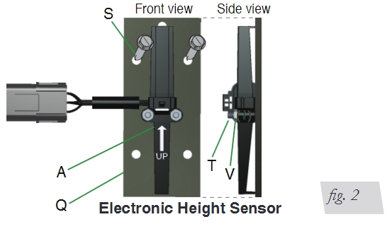
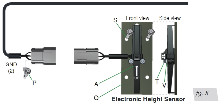
ATTACHING THE ELECTRONIC HEIGHT SENSOR (EHS) 1. Using the socket cap screws (T) and nylon lock nut (V), attach the electronic height sensor (A) to the bracket (Q). (Fig. 2)
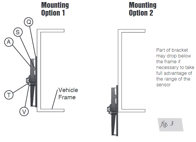
2. Choose a mounting location along the frame rail for the height bracket and sensor. (Fig. 3) STAY CLEAR OF ANYTHING THAT MAY COME IN CONTACT WITH THE HEIGHT SENSOR WHILE THE SUSPENSION TRAVELS IN JOUNCE AND COMPRESSION.
3. Use the self-tapping screws (S) to mount bracket to the frame at the chosen location. (Fig. 3)
ATTACHING THE MAGNET AND MOUNTING BRACKET THE MAGNET HAS A STRONG PULL. USE CARE WHEN HANDLING TO AVOID PINCHING FINGERS OR SKIN.
1. Place the supplied U-bolt (L) around the leaf springs near the previously mounted height sensor in either of the two configurations. (Fig. 4) 2. Using Figure 4 as a guide, choose the best mounting method for this vehicle. When choosing the mounting method, keep in mind that the center of the magnet must align with the height sensor when the vehicle is at ride height. The magnet and the height sensor must be between 1”- 1 1/2” apart.
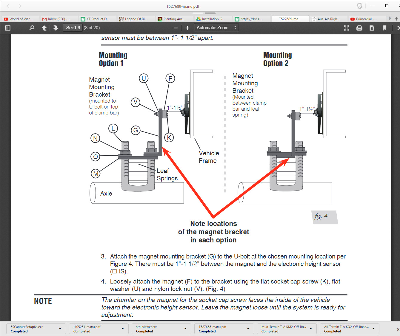
3. Attach the magnet mounting bracket (G) to the U-bolt at the chosen mounting location per Figure 4. There must be 1”-1 1/2” between the magnet and the electronic height sensor (EHS).
4. Loosely attach the magnet (F) to the bracket using the flat socket cap screw (K), flat washer (U) and nylon lock nut (V). (Fig. 4) The chamfer on the magnet for the socket cap screw faces the inside of the vehicle toward the electronic height sensor. Leave the magnet loose until the system is ready for adjustment.
5. Align the center of the magnet with the white line on the height sensor. Once the magnet is in line, securely tighten the bracket mounting hardware.
INSTALLING THE ELECTRICAL COMPONENTS
1. Run the harness from the cab/battery to the exhaust solenoid/compressor location. It may be necessary to drill a hole so that the harness can easily pass through from the cab/engine compartment to the vehicle frame. Place a grommet or silicone sealant around any holes that the harness passes through to protect it from abrasive surfaces.
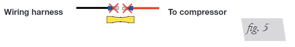
2. Cut off the male terminals on both the harness black wire and compressor red wire. Use heat shrinkable butt connector (R) to connect the two wires together. Apply heat using a heat gun. (Fig. 5)
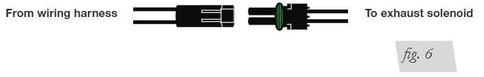
3. Connect the two-pin connector from the solenoid to the mating connector on the main harness. (Fig. 6)
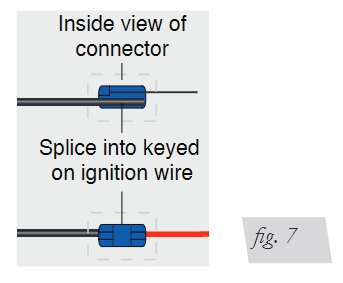
4. Using the wire tap provided with the harness, splice the red wire connected to the 5-amp fuse that feeds the Electronic Height Sensor to a keyed ignition source. (Fig. 7)
5. Connect the 6-pin connector on the wiring harness to the mating connector on the Electronic Height Sensor. (Fig. 8)
Installation Diagram
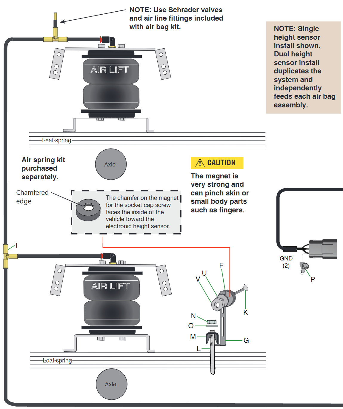
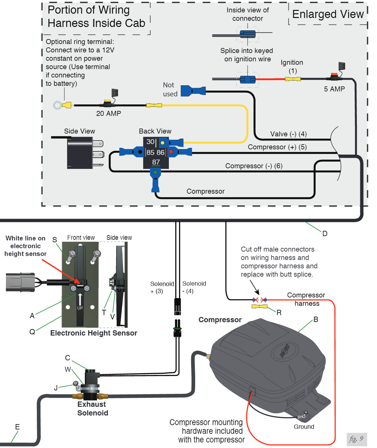
6. Attach the terminal end of the white ground wire on the harness to a clean section of the frame rail using the provided self-tapping screw (P). (Figs. 8 & 9) Grind off the paint, surface rust and debris if connecting the ground directly to the frame to ensure a good connection.
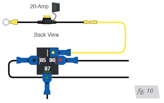
7. Using the butt connector supplied with the harness, attach yellow 12-gauge wire feeding the relay terminal 30 to one end of the 20-amp fuse holder supplied with the harness.
8. If choosing to connect the black wire directly to the battery, use the ring terminal supplied with the harness and attach it to the other end of the fuse holder wire. (Fig. 10)
9. Attach to an appropriate battery-direct 12-volt source on the vehicle. A direct connection to the battery is suggested.
ADJUSTING THE SYSTEM
1. Make sure that the distance between the face of the magnet and the height sensor is between 1” and 1 1/2”. (Fig. 4)
2. The screw in the center of the magnet must be in line with the white line on the height sensor when the vehicle is at ride height. THIS MAGNET IS VERY STRONG. IT IS POSSIBLE FOR THE MAGNET TO PINCH FINGERS AND SKIN BETWEEN ANOTHER MAGNET OR METAL OBJECT. CARE SHOULD BE TAKEN WHEN HANDLING THE MAGNET.
3. Adjust the suspension by moving the magnet up or down in the slotted mounting bracket. It is recommended that the magnet be set a half inch below the white line on the electronic height sensor to start. Take a reference measurement from the ground to the rear bumper or the wheel well.
4. Turn the ignition key to the on position and determine if it it reaches the desired height. If not, adjust the magnet and check it again. The preferred method of adjusting the system would be to load the vehicle, then adjust the magnet so that the suspension obtains the desired height. Usually a good starting point would be to set the vehicle (using the magnet) at a level ride height, or one inch below the stock curb height unladen (using the measurement taken in step 3). There is a 15- to 20-second delay in the system. Once the magnet is set in position and no movement is detected by the Electronic Height Sensor, it will take 15-20 seconds for the compressor or the exhaust solenoid, to turn on and level the vehicle by inflating, or deflating, the air springs in the suspension. Once the desired ride height is obtained, tighten the magnet mounting screw snug. Do not overtighten. CHECKING THE SYSTEM 1. Inspect all air line connections for leaks by using a solution of 1/5 dish soap to 4/5 water. Should a leak be detected in a push-lock-fitting, reinstall the air line to the fitting. Make sure the air line is cut off squarely and that the air line is completely pushed into the fitting. (Fig. 1) 2. If the compressor or the solenoid fails to function, check the 20- and 5-amp fuses along with ground connections. Repair and replace as necessary.