FREE 1 to 3-Day Delivery on Orders $119+ Details
How to Install Belltech Street Performance Shock Set for +1 in. to - 3 in. Front / 2 in. Rear Drop (09-13 2WD) on your Ford F-150
Installation Time
3 hours
Tools Required
- Blocks and Wheel chocks
- Ratcheting Socket Set
- Safety Glasses
- Torque Wrench
- Properly rated floor jacks and support stands
- Combination Wrench set
- Spring Compressor
- Ball Joint Puller
Shop Parts in this Guide
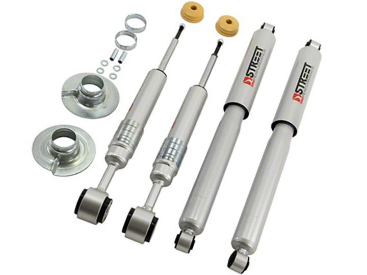
- Belltech Street Performance Front and Rear Shocks for +1 to -3-Inch Front / 2-Inch Rear Drop (09-13 2WD F-150)
- Belltech Street Performance Front Strut for +1 to -3-Inch Drop (04-13 2WD F-150)
- Belltech Stage 3 Lowering Kit with Street Performance Shocks; +1 to -3-Inch Front / 2-Inch Rear (09-13 2WD F-150 w/ Short Bed)
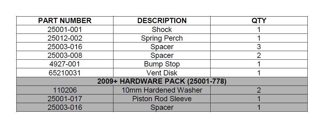
Note: Confirm that all of the hardware listed in the parts list is in the kit. DO NOT begin this installation if any part is missing. Read the instructions thoroughly before beginning this installation.
Warning: DO NOT work under a vehicle supported by only a jack. Place support stands securely under the vehicle in the manufacturer’s specified locations unless otherwise instructed.
Warning: DO NOT drive the vehicle until all work has been completed and checked. Torque all hardware to values specified.
Reminder: Proper use of safety equipment and eye/face/hand protection is absolutely necessary when using these tools to perform procedures!
Note: It is very helpful to have an assistant available during the installation process.
Note: We DO NOT RECOMMEND using wheel ramps while performing this installation.
NOTE: FOR 2009-2012 VEHICLES, PLEASE NOTE AMMENDMANT CHANGES IN THE INSTALLATION INSTRUCTION AS DENOTED IN THE GRAY TEXT BOX.
1. PREPERATION
1a) Open the hardware kit and remove all of the contents. Refer to the parts list (Page 6) to verify that all parts are present. Do not begin work if parts are missing.
1b) Park the vehicle on a smooth, level concrete or seasoned asphalt surface and activate the parking brake. Block the REAR wheels of the vehicle with appropriate wheel chocks; making sure the vehicle’s transmission is in 1st gear (manual) or “Park” (automatic).
1c) Lift the FRONT wheels of the vehicle off the ground using a properly rated floor jack. Place support stands, rated for the vehicle’s weight and in the factory specified locations. Refer to the vehicle Owner’s Manual. Prior to lowering the vehicle onto the stands, make sure the supports will securely contact the chassis. Remove the front wheels.
It is very important that the vehicle is properly supported during this installation to prevent personal injury and chassis damage. Make sure that the support stands are properly placed prior to performing the following procedures. We DO NOT RECOMMEND using wheel ramps while performing this installation.
2. REMOVING THE O.E.M. FRONT STRUT
2a) Unbolt the brackets securing the ABS lines to the upper control arm. Make sure this line is not stretched or tangled in subsequent steps. On some models it may also be necessary to remove the ABS line bracket from the frame to prevent tension on the lines as well.
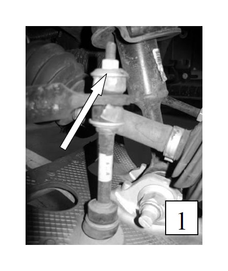
2b) Un-bolt the top mounting nuts to the sway bar end-links to allow the control arm to move independently of the end- link. (photo 1)
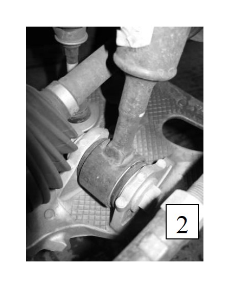
2c) Loosen and remove the bottom mounting bolt of the spring/strut assembly. (photo 2)
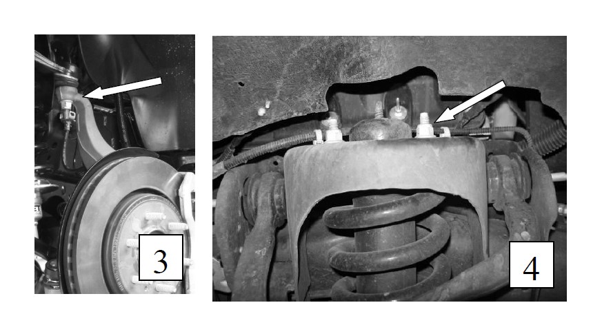
2d) Loosen and remove nut securing the upper ball-joint to the spindle. Secure the spindle and brake assembly to the chassis using a strap so that the ABS line is not stretched once the ball-joint is broken free. Break free the ball-joint using the proper ball joint puller or by tapping the side of the spindle with a hammer. Once free from the upper control arm, push the spindle, brake and lower control arm assembly down to free it from the lower shock mount and out of the way while still supported by the strap. (photo 3)
2e) Remove the top three mount bolts of the front spring/strut assembly. (photo 4) Slide the spring and shock assembly down and out of the front suspension. For ease of reinstallation, mark the outboard side of the spring and upper shock mount with a paint pen.
3. OEM STRUT DISASSEMBLY
CAUTION!The coil springs is held in place under extreme compression. Belltech recommends the use of a heavy duty spring compression suitable for truck springs to perform this step. If unsure of your spring compressor capabilities, take this to a professional installer. Use caution during the following steps to avoid personal injury and/or damage to vehicle.
3a) Mount the entire spring/strut assembly in the spring compressor fixture. To ease the installation of the new strut, mark a white line down the center of the assembly for alignment purposes only showing the front of the top mount. Note the orientation of the upper mount relative to the bottom shock eyelet.
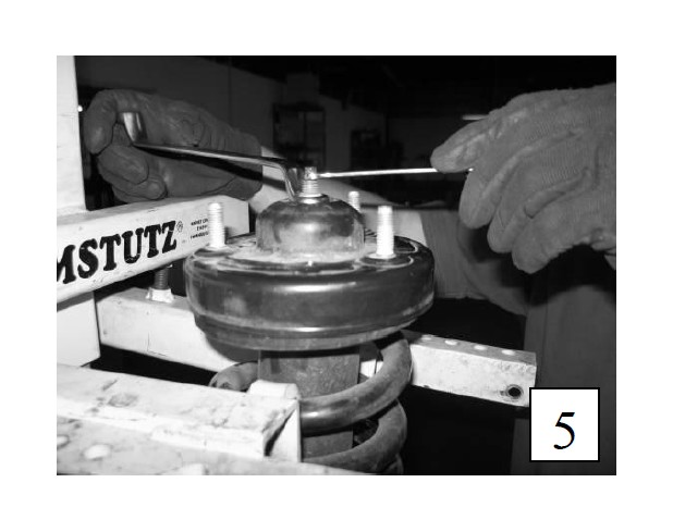
3b) Compress the spring until the spring is no longer touching the upper mount. Using an open end 17mm wrench and a smaller 8mm wrench to prevent the piston shaft from spinning, loosen and remove the top nut. (photo 5) THE STOCK SHOCK WILL DROP TO THE GROUND IF NOT SUPPORTED. Remove the OEM shock.
4. BELLTECH STREET PERFORMANCE STRUT ASSEMBLY
4a) Depending on the ride height desired, install the required spacers for the BELLTECH Lifting & Lowering Shock. REFER TO THE TABLE IN GRAY FOR 2009-2012 VEHICLES.
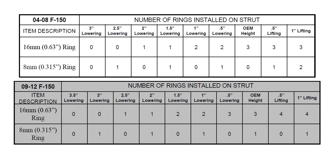
Caution: The Belltech 25001 is designed for use with the stock vehicle spring ONLY. Do not lower the vehicle below the lowest specification on each chart as the vehicle may not be able to be aligned and the performance of the shock may be greatly decreased.
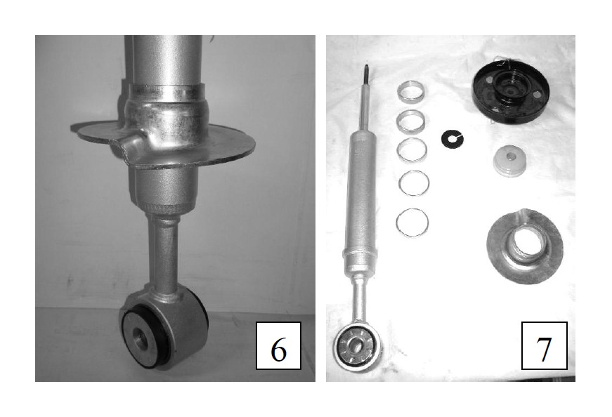
4b) Slide the specified number of spacer rings onto the Belltech Street Performance shock body. Slide the supplied Belltech spring perch on-top of the spacer rings. (photo 6) Finally install the thin black plastic vent disk at the base of the piston rod followed by the progressive bump stop with the smaller end facing down.
4c) Position the new shock inside the still compressed stock spring and upper spring perch. Secure the shock and mount with the supplied Nyloc using an open end 17mm wrench and a smaller 7mm wrench. Uncompressing the spring when the shock, spring and upper spring perch are correctly oriented.
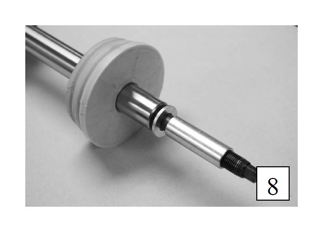
NOTE: FOR 2009 - 2012 VEHICLES, INSTALL THE SUPPLIED 10mm WASHER AND SLEEVE FOUND IN THE 2009 HARDWARE PACK PRIOR TO POSITIONING THE SHOCK INSIDE THE SPRING AND UPPER SPRING PERCH (photo 8). ALSO PLACE AN ADDITIONAL WASHER ONTOP OF THE PISTON ROD AND UPPER MOUNT PRIOR TO THREADING THE SUPPLIED NYLOC WASHER. TIGHTEN THE NYLOC TO 33 FT LB USING 17mm WRENCH AND 7 mm SOCKET.
5. RE-INSTALLATION OF FRONT SUSPENSION
5a) Re-install on the new strut assembly the same way the O.E.M. strut was removed.
5b) In reverse order, follow Step 2 using the OEM nuts and bolts
5c) Check to see that all bolts are torqued to factory specifications..
6. ALLIGNMENT MONDIFICATION
This process is not normally needed for the Belltech 2” drop but is recommended when lowering more than 2”. This process will allow for additional adjustment to obtain factory spec alignment. If lowering vehicle less than 2”, please skip to step 7.
6a) Remove the bolts from both lower control arms.
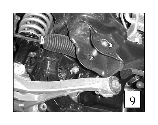
6b) Pull the lower control arms down and out of the way. (photo 9).
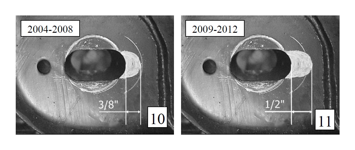
6c) Insert a stock bolt in the slot locations on the lower control arm mount, position the bolt against the inner slot side then scribe a line along the bolt flange (Photo 9). This should be 3/8” from the original alignment slot. It is helpful to outline the profile of the bolt flange so it can be easily followed while cutting. Perform this marking technique on all eight slots.
Note: For 2009-2012 vehicles this slot can be expanded another 1/8” for a total of 1/2” (photo 11)
6d) Using a die grinder and carbide metal cutting bit remove the material outlined.(photo 10)
6e) Once all the holes have been slotted, remove any burrs then reattach the lower control arms.
7. FINALIZING THE INSTALLATION
7a) All hardware being fastened to the vehicle’s original fastening points should be torqued to the proper specifications. To prevent chassis damage, never over-torque the hardware.
7b) Check brake hoses and other components for any possible interference.
7c) Lift the vehicle and remove the support stands. Carefully lower the vehicle to the ground.
7d) Immediately test-drive the vehicle in a remote location so that you can become accustomed to the revised driving characteristics and handling. Be aware that the vehicle will handle substantially different now that it has been modified.
7e) Installation is complete. Check all of the hardware and re-torque at intervals for the first 10, 100, 1000 miles.