FREE 1 to 3-Day Delivery on Orders $119+ Details
How to Install Corsa 3 in. Sport Cat-Back Exhaust w/ Twin Polished Tips - Single Side Exit on your F-150
Installation Time
2 hours
Tools Required
- 13mm deep socket
- 14mm deep socket
- 15mm deep socket
- Ratchet
- 14mm wrench
- Penetrating lubricant
- Safety glasses
- Torque wrench
- Safety Glasses
- Grommet Pullers
- 13mm Socket
- 12" Ratchet Extension
- 10mm Socket
- Torque Wrench
- 15mm Socket
- Soap & Water Solution
- 3/8” Ratchet
Shop Parts in this Guide
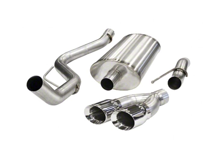
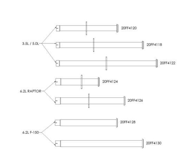
- Corsa Performance Sport Single Exhaust System with Twin Polished Tips; Side Exit (11-14 6.2L F-150 Raptor)
- Corsa Performance Xtreme Single Exhaust System with Twin Polished Tips; Side Exit (11-14 6.2L F-150 Raptor)
- Corsa Performance Sport Single Exhaust System with Twin Black Tips; Side Exit (11-14 6.2L F-150 Raptor)
- Corsa Performance Xtreme Single Exhaust System with Twin Black Tips; Side Exit (11-14 6.2L F-150 Raptor)
Please take time to read and understand these installation instructions.
CORSA recommends that the installation of this system be performed by a qualified service center or professional muffler installer who has the necessary equipment, tools and experienced personnel. However, if you decide to perform this install, the use of a hoist and an additional person will be required.
CAUTION: Never work on a hot exhaust system. Allow time for the vehicle to cool. Always wear eye protection when working under a vehicle.
FOR SPORT SYSTEM ONLY PROCEED TO PAGE 5
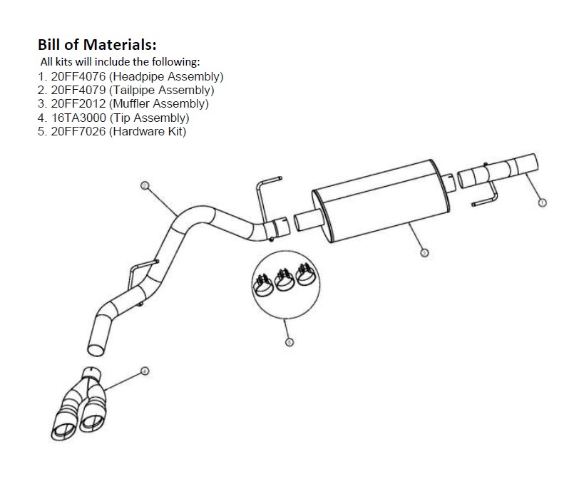
Please confirm that all parts are present before beginning the factory exhaust system removal and CORSA exhaust system installation.
Removal of Stock System
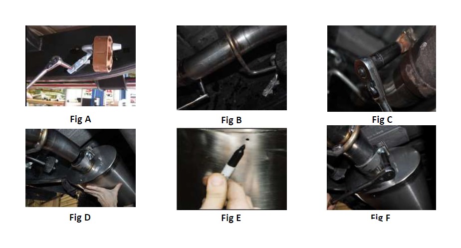
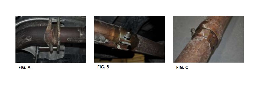
1. Remove both bolts on the connecting flange of the resonator using a 13mm socket and ratchet. (See Fig A.)
2. Loosen the clamp on the end opposite of the flange using a 15mm socket. (See Fig B.)
Note: Using a penetrating lubricant on the clamped area may aide in the removal of the resonator.
3. If removing resonator from completely stock system, rotate the resonator until the retaining boss on the stock exhaust is aligned with the slot. (See Fig C.) (If removing stock resonator from the Corsa Performance cat-back exhaust, there will be no retaining boss to align.)
4. The resonator is now ready to be removed from the vehicle.
Installation of CORSA Exhaust System:
NOTE: Apply the anti-seize lubricant (supplied) to the threads ONLY of all the clamps and flange bolts. Failure to follow this procedure can cause nuts to seize on clamps and potentially destroy threads. After applying anti-seize lubricant, be sure to thoroughly clean your hands, as lubricant will tarnish stainless steel. All clamps should be tightened using a properly calibrated Torque Wrench. Using an air impact gun will damage the clamp and reduce its ability to effectively seal the joint. It may also cause the joint to separate, thereby causing damage to your exhaust system and to your vehicle.
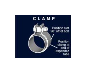
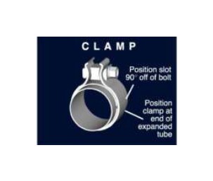
NOTE: Align all clamps so that the center of the clamp bolt is 90 degrees from the notch in the pipe. (See Fig. CLAMP)
1. Locate the CORSA resonator delete assembly and hardware.
2. Those who purchased kit number 14755 or 14756 need to now locate the two bolt hole flange supplied in the hardware kit, and slide it over the pipe. Those who purchased all other kits proceed to step 3.
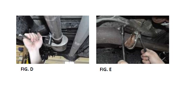
3. Install the supplied clamp onto the end of the pipe and slide the resonator delete assembly onto the muffler intermediate pipe. (See Fig. D)
4. Align the machined gasket of the resonator delete to the factory flange routing of the truck and slide the two bolt hole flange to the front of the pipe. Install the supplied hardware using a 14mm socket, wrench, and ratchet. Do not fully tighten at this point. (See Fig. E)
5. Snug the supplied clamp with a 15mm deep socket and ratchet. Do not fully tighten at this point.
6. Once satisfied with the position of the pipe, tighten the hardware at the flange to 40.5 ft-lbs then tighten the TORCA clamp to 45 ft-lbs using a torque wrench. Make sure clamps are positioned and tightened as shown. (See Fig CLAMP)
Please confirm that all parts are present before beginning the factory exhaust system removal and CORSA exhaust system installation.
Removal of Stock System
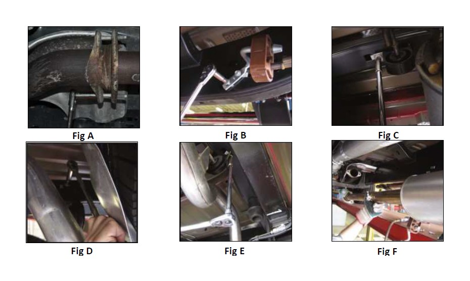
1. Remove both bolts that secure the flange connection on the factory center pipe using a 13mm socket and ratchet. (See Fig. A)
2. Unbolt the muffler hanger mount from the chassis using a 10mm socket and ratchet. (See Fig. B)
3. Unbolt the front tailpipe hanger mount from the chassis using a long extension, and a 10mm socket and ratchet. (See Fig. C)
4. Unbolt the rear tailpipe hanger mount from the chassis using a long extension, and a 10mm socket and ratchet. (See Fig. D & E) Carefully remove the entire stock exhaust system from the vehicle by moving it forward and down past the rear axle. (See Fig. F) The stock exhaust is removed as one piece and is fully intact.
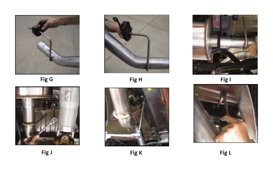
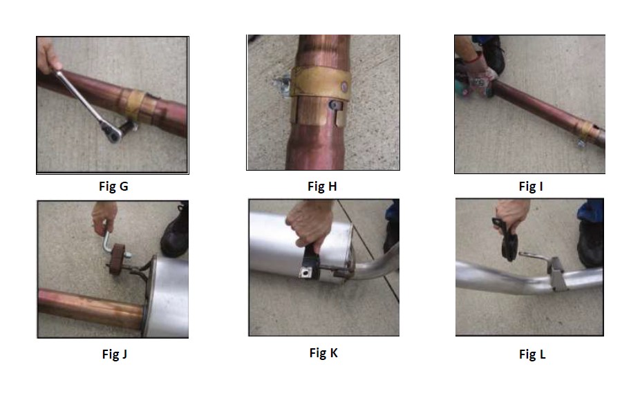
5. With the stock exhaust on the ground, loosen the clamp on the factory center pipe using a 15mm socket and ratchet. (See Fig G) Rotate the center pipe until the retaining boss on the stock exhaust is aligned with the slot and then remove the center pipe from the rest of the factory system. (See Fig. H & I)
6. Remove the factory muffler and tailpipe hangers from the rubber isolators on the hanger mounts using a grommet puller or a similar device. (See Fig. J,K, & L) Note the position and orientation of each hanger mount. Set aside the muffler and tailpipe hanger mounts and the retaining bolts to be reused during the installation process.
NOTE: The use of a soapy water solution may aid in the removal and later installation of the hangers in the rubber isolators.
7. Removal is now complete. Installation of your CORSA Performance exhaust system can now begin.
NOTE: The supplied double edge clamps in this system will crush and permanently deform the exhaust piping as they are tightened. DO NOT tighten these clamps any more than is necessary to lightly hold the exhaust components in place, until the very end of this installation process. It will be difficult or impossible to make any positional or Rotational adjustments to the exhaust system after these clamps have been tightened down.
VERY IMPORTANT: Align all clamps so that the open edge of the clamp bracket is parallel and aligned with the notch in the pipe, and the outside edge of the clamp bracket is approximately 1/8” from the end of the pipe expansion. Failure to properly position or orient the clamps could result in a weak clamping load, or even a potential leak at the clamp joints.
1. Remove all exhaust system components from the shipping carton, including the two supplied clamps.
2. Locate the factory center pipe that was disconnected during the removal process, along with the two 13mm mounting bolts. Align the flanges, and snug tighten both of the bolts using a 13mm socket and ratchet. Make sure that the center pipe is oriented so that the clamp bolt is accessible.
3. Locate the intermediate pipe assembly, and the muffler hanger mount, along with the two 10mm mounting bolts. Align the hanger mount with the mounting holes in the chassis, and secure with a 10mm socket and ratchet.
Note the proper orientation of the muffler hanger mount as shown in the figure. Torque the 10mm bolts to factory specs. (See Fig. A) NOTE: Using a soapy water solution on the muffler hanger grommet at this time will make the following step much easier to accomplish.
4. Insert the intermediate pipe hanger into the factory muffler hanger grommet, and then move the front end of the intermediate pipe forward into the factory center pipe. Seat the front end of the intermediate pipe assembly into the center pipe expansion, past the end of the factory clamp. Use a rubber mallet if necessary to make sure the pipe is properly seated. The end of the hanger will be flush with the end of the hanger mount rod when the depth of the pipe is correct. (See Fig. B)
5. Rotate the intermediate pipe assembly until the grommet is straight up and down, and the hanger is directly underneath the hanger mount rod. Snugly tighten the factory clamp on the center pipe using a 15mm socket and ratchet. (See Fig. C)
6. Locate muffler, and one of the supplied clamps. Slide the expanded end of the muffler inlet pipe onto the intermediate pipe. (See Fig. D)
IMPORTANT: Make sure that the small drain hole in the rear of the muffler is facing straight downwards when the muffler is installed. (See Fig. E)
7. Secure the muffler in place with the supplied clamp as shown, using a 15mm socket and ratchet, making sure to only tighten the clamp nuts just enough to hold the muffler onto the intermediate pipe. Note the position and orientation of the clamp. (See above clamp notes & See Fig. F)
NOTE: The unbolted tailpipe hanger assemblies from the removal process should now be installed onto the corresponding hangers on the tailpipe by pushing the rubber grommets onto the hangers. Once again, a soapy water solution will aid in this installation process. (See Fig. G & H)
8. Locate the rear tailpipe assembly, along with the 10mm hardware to secure the hanger mounts, and the last of the supplied clamps. Slide the expanded end of the tailpipe onto the outlet of the rear muffler. (See Fig. I) Align the hanger mounts with the mounting holes in the chassis, and secure with a 10mm socket and ratchet, and a long extension. Note the proper orientation of the muffler hanger mounts as shown. Torque the 10mm bolts to factory specs. (See Fig. J,K, & L)
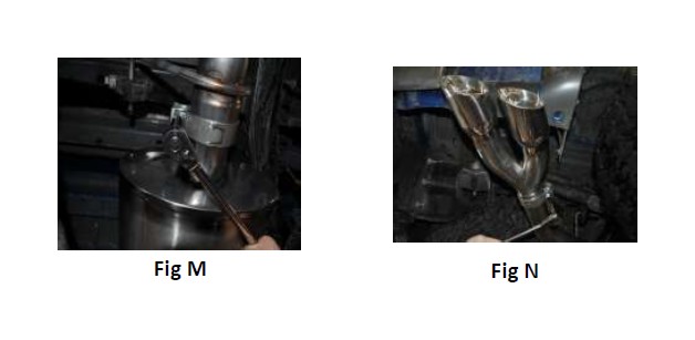
9. Rotate the rear tailpipe assembly until the rearmost section of the pipe is horizontal, and then secure it with the supplied clamp as shown, using a 15mm socket and ratchet, making sure to only tighten the clamp nuts just enough to hold the tailpipe onto the muffler. (See Fig. M)
10. Locate the tip assembly. Slide a clamp over the expanded end of the tip, and onto the end of the tailpipe. Snugly tighten the clamp as shown using a 15mm socket and ratchet, making sure to only tighten the clamp enough to hold the tip in place on the tailpipe. (See Fig. N)
11. Visually inspect the exhaust system position, tip alignment, clamp orientation and position, and exhaust pipe clearance. Make any necessary adjustments at the slip joints.
12. Fully tighten the 13mm bolts on the center pipe flange. Torque to the factory specs. Next, tighten the clamp on the factory center pipe to 45 ft-lbs.
13. Start at the front of the vehicle, and tighten the nuts on the two supplied clamps on each side of the muffler. Torque the nuts on the clamps to 45 ft-lbs. Finally, tighten the clamp that is built into the tip to 45 ft-lbs.
14. It is STRONGLY SUGGESTED that all clamps be checked and re-tightened (if necessary) to the recommended torque after initial road testing of the vehicle, as thermal cycling has occurred on the system. Please wait until system has fully cooled to conduct this process.