 FREE 1 to 3-Day Delivery on Orders $119+ Details
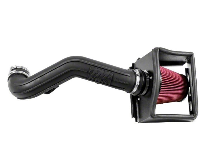
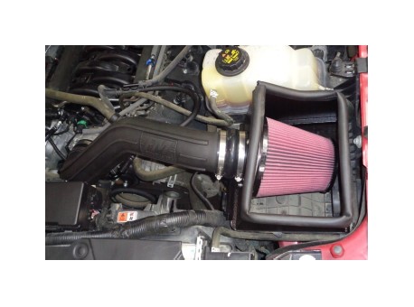
How to Install Flowmaster Delta Force Cold Air Intake (11-14 5.0L) on your Ford F-150
Shop Parts in this Guide
REVIEW THE INSTRUCTIONS AND VERIFY THE KIT CONTENTS:
1. Please take a moment to read and understand these instructions before installing your Flowmaster cold air intake kit.
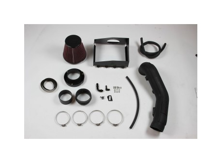
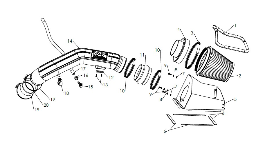
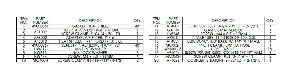
2. Use the parts drawing and list (front page) to verify your kit’s contents.
In the unlikely event that any parts are missing, please contact FLOWMASTER Technical Support for replacements.
REMOVE THE FACTORY AIR INTAKE SYSTEM:
NOTES
• We highly recommend that you retain all factory air intake system parts.
• Please refer to vehicle manufacturer’s recommendations regarding removal of factory components.
• Disconnecting the negative battery cable erases pre‐programmed electronic memories. Write down all memory settings before disconnecting the negative battery cable. Some radios will require an anti‐theft code to be entered after the battery is reconnected. The anti‐theft code is typically supplied with your owner’s manual. In the event your vehicle’s anti‐theft code cannot be recovered, contact an authorized dealership to obtain your vehicle’s anti‐theft code.
3. Turn off the vehicle’s ignition and disconnect the negative battery cable.
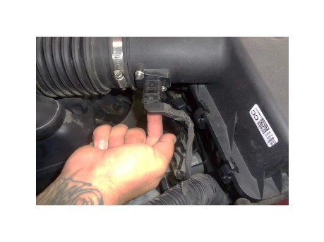
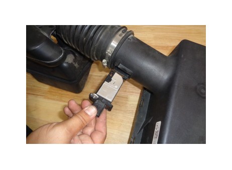
4. Disconnect the mass airflow (MAF) sensor plug by pulling the locking tab (on the bottom of the plug) away from the sensor until it stops, then pulling the plug straight off the sensor.
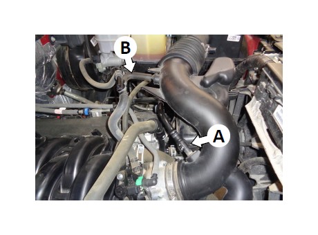
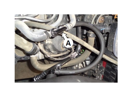
5. On the PCV hose connector (A), release the latch and disconnect the hose from the intake duct. Disconnect the EVAP hose (B) from both the intake duct and the check valve.
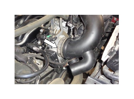
6. Loosen the screw clamp securing the air intake duct to the throttle body.
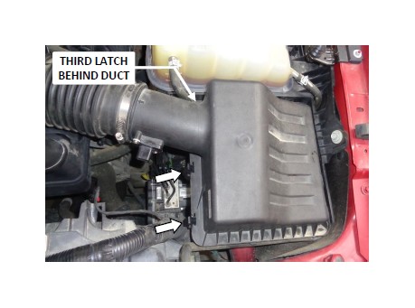
7. Release the three airbox cover latches.
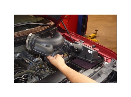
8. Separate the intake duct from the throttle body, then remove the assembled duct and airbox cover from the vehicle. Remove the stock air filter.
9. Remove the MAF sensor from the airbox cover, then remove the stock gasket from the sensor. CAUTION: The sensor is delicate! Handle it with care, and store it in a safe location until reinstallation.
ASSEMBLE AND INSTALL YOUR FLOWMASTERCOLD AIR INTAKE SYSTEM:
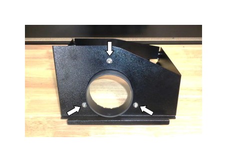
10.Assemble the air filter adapter (4) to the heat shield (5) using the M6 screws (9), lock washers (8) and flat washers (7).
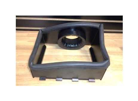
11.Attach the gasket (1) to the heat shield. Firmly press the gasket onto the heat shield, gradually working your way around. When you return to the starting point, use metal‐cutting shears to trim the gasket to length.
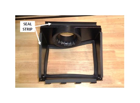
12.Cut the adhesive seal strip (6) to length as required, and apply it to the four edges of the heat shield.
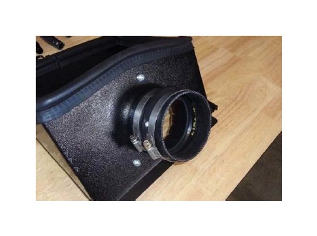
13.Slip the 2 larger screw clamps (10) onto the flex coupler (11). Install the large end of the coupler onto the air filter adapter, pushing it flush against the heat shield. Tighten only the filter adapter clamp at this time. (Leave the other clamp loose.)
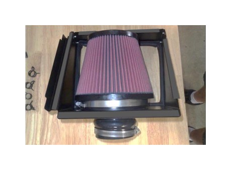
14.Slip screw clamp (3) onto air filter (2), then install the filter on the filter adapter and tighten the clamp.
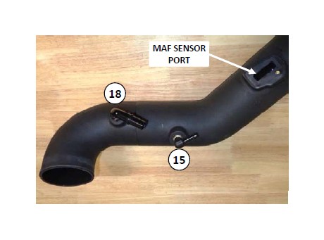
15.Apply 2 wraps of nylon thread tape to the threads of the 5/8" quick connect elbow (18) and the 3/8" barbed elbow (15). Install the elbows in the intake tube (14), oriented approximately as shown.
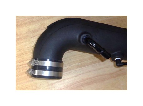
16.Slip the 2 smaller screw clamps (19) onto the straight coupler (20), then push the coupler onto the intake tube. Snug (do not tighten) only the tube clamp at this time. (Leave the other clamp loose.)
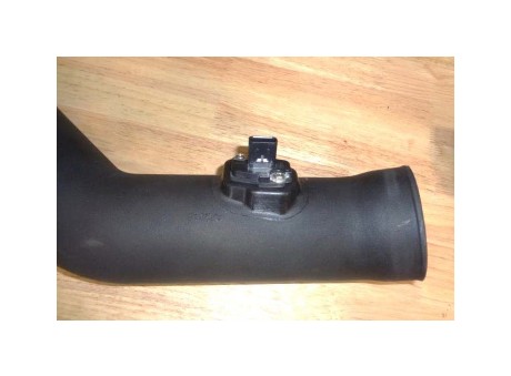
17.Place the MAF sensor gasket (12) over the sensor, ensuring correct orientation. Then install the sensor in the intake tube, using M4 screws (13).
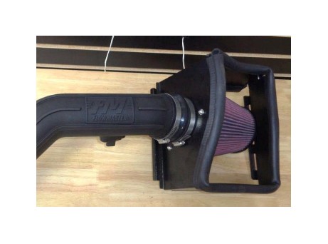
18.Assemble the intake tube and heat shield. Snug the tube clamp (do not tighten at this time).
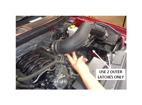
19.Insert the four tabs on the heat shield into the slots on the airbox. Lower the intake tube and install the straight coupling on the throttle body. Secure the heat shield to the airbox with the two outer latches. NOTE: The center latch is not used.
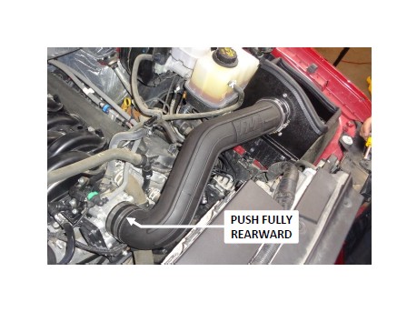
20.Push the straight coupling up against the throttle body and tighten the throttle body clamp. Then center the intake tube between the couplers (equal amounts of tube inserted in each coupler), and tighten the last two screw clamps.
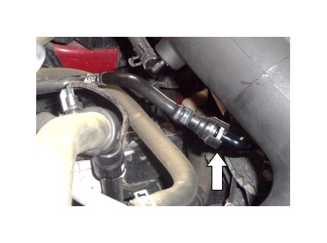
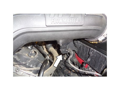
21.Push one end of the 3/8" hose (17) onto the EVAP check valve (A). Route the hose to the barbed elbow as shown and cut it to length. Push the hose onto the elbow, and secure it with the pinch clamp (16).
22.Connect the PCV hose to the quick‐connect elbow, close the latch on the connector, and check the security of the connection.
23. Reinstall the MAF sensor plug on the sensor, close the locking tab, and verify that the connection is secure.
Congratulations, the installation of your FLOWMASTER cold air intake kit is now complete!
