 FREE 1 to 3-Day Delivery on Orders $119+ Details
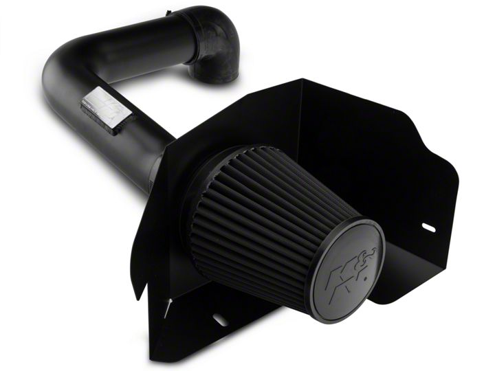
How to Install a K&N Series 71 Blackhawk Induction Cold Air Intake on your Ford F-150
Installation Time
1 hours
Tools Required
- Flat Blade Screwdriver
- Ratchet
- 10mm Socket
- 13mm Socket
- 9/16” Socket
- Torx T20 Driver
- 2.5mm Allen Wrench
- 4mm Allen Wrench
- Drill
- 5/8” Drill Bit
- 1/8” Drill Bit
- Phillips Screwdriver
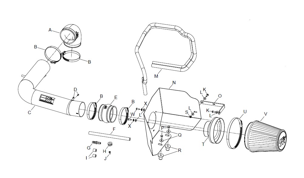
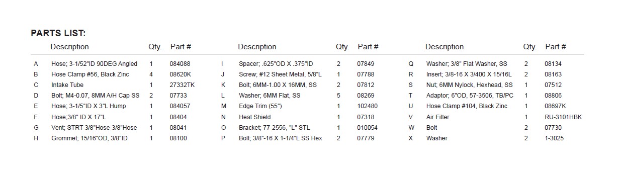
Shop Parts in this Guide
NOTE: FAILURE TO FOLLOW INSTALLATION INSTRUCTIONS AND NOT USING THE PROVIDED HARDWARE MAY DAMAGE THE INTAKE TUBE, THROTTLE BODY AND ENGINE.
TO START:
1. Turn off the ignition and disconnect the negative battery cable.
NOTE: Disconnecting the negative battery cable erases pre-programmed electronic memories. Write down all memory settings before disconnecting the negative battery cable. Some radios will require an anti-theft code to be entered after the battery is reconnected. The anti-theft code is typically supplied with your owner’s manual. In the event your vehicles’ anti-theft code cannot be recovered, contact an authorized dealership to obtain your vehicles anti-theft code.
2. Disconnect the mass air sensor electrical connection.
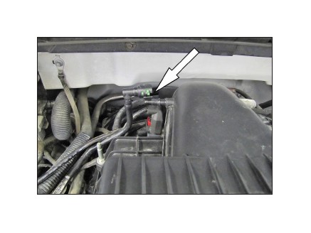
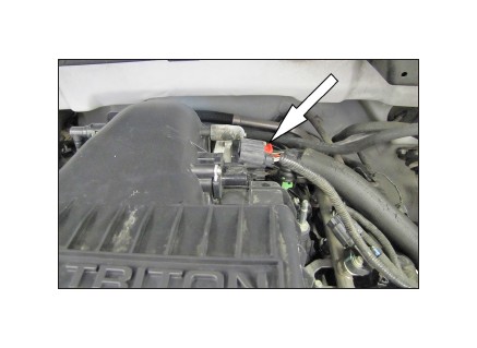
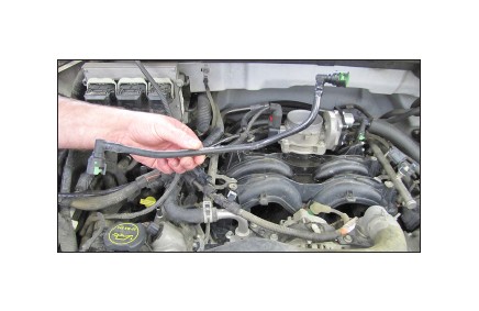
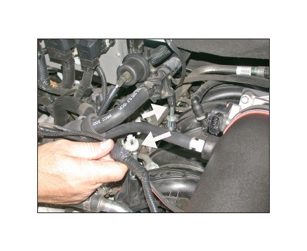
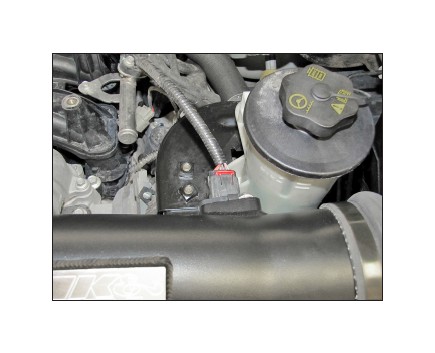
3. Disconnect the crank case vent line as shown.
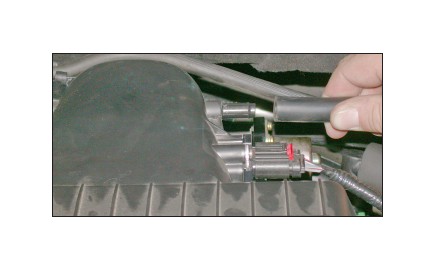
4. On vehicles equipped with a Brake Booster/EVAP vent line, disconnect the vent line from the air box.
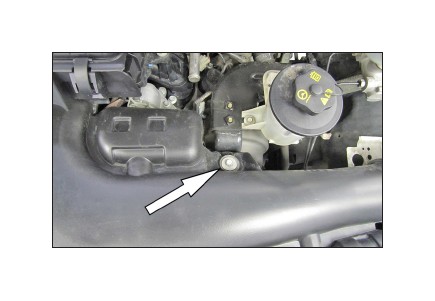
5. Remove the bolt shown securing the intake snorkel to the bracket.
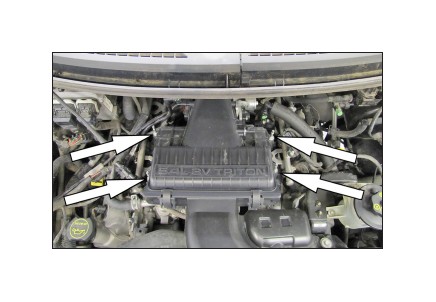
6. Remove the four bolts securing the air filter housing to the intake manifold.
NOTE: Some vehicles may have a heater hose and wiring harness attached to the right side air box mounting studs.
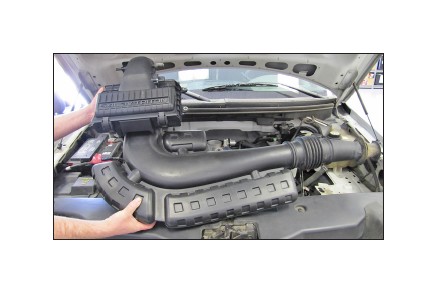
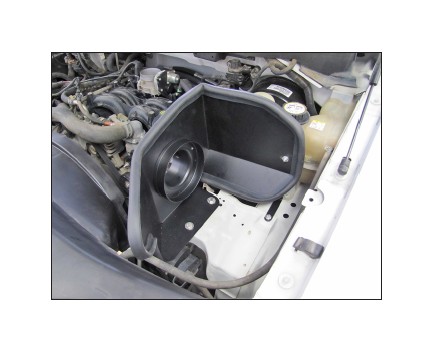
7. Remove the complete air box and intake snorkel assembly as shown.
8. On vehicles with the heater hose and wiring harness attached to the air box studs, place a spacer under the two right side air box studs and reinstall the studs into the original location.
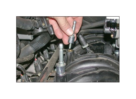
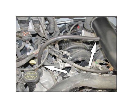
9. Release the crank case vent hose from the valve cover port and then remove the crank case hose from the vehicle.
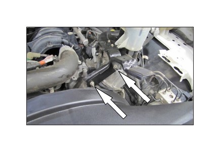
10. Remove the two nuts securing the intake snorkel bracket, then remove the bracket and reinstall the bottom nut.
11. Install the filter adapter into the heat shield as shown and secure with the provided hardware.
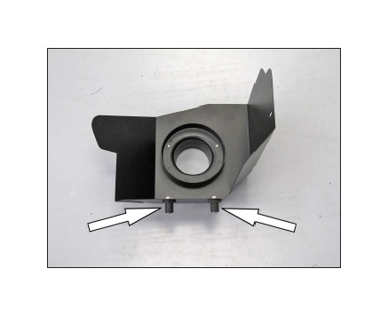
12. Install the two provided inserts onto the heat shield as shown and secure with the provided hardware.
NOTE: Do not completely tighten at this time.
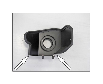
13. Install the provided edge trim onto the heat shield as shown.
NOTE: Some trimming of the edge trim will be necessary.
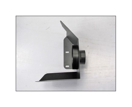
14. Install the heat shield mounting bracket (010054) onto the heat shield as shown and secure with the provided hardware.
NOTE: The long leg of the bracket attaches to the heat shield.
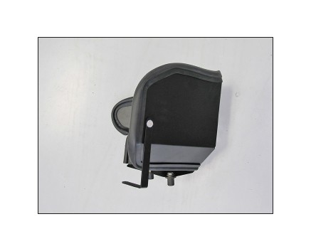
15. Set the heat shield onto the air box mounting plate so the inserts go into the mounting grommet holes. Secure the heat shield with the insert bolts and with the bracket to the inner fender with the provided hardware.
NOTE: Some vehicles may not be equipped the a weld nut in the Air filter housing mounting plate. In this case, drill an 1/8”hole in the plate and then install the provided self-taping sheet metal screw.
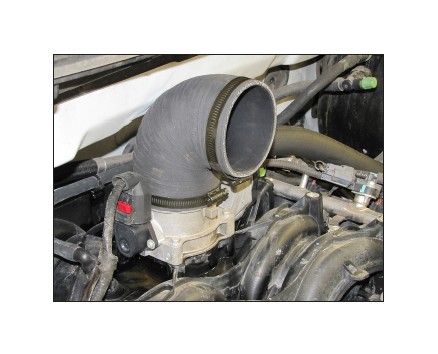
16. Install the provided 90° hose onto the throttle body and secure with the provided hose clamp.
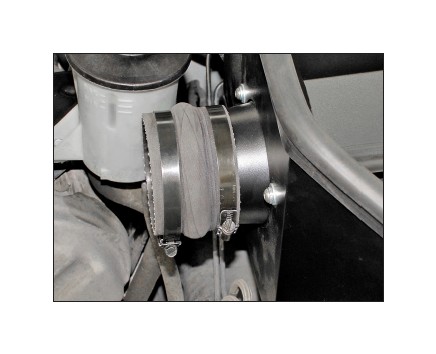
17. Install the provided hump hose (084057) onto the filter adapter and secure with the provided hose clamp.
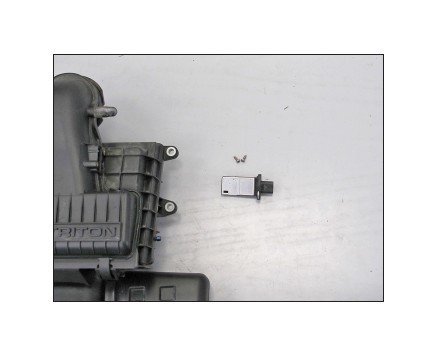
18. Remove the two screws securing the mass air sensor into the stock air filter housing and then remove the sensor from the vehicle.
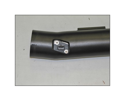
19. Install the mass air sensor into the K&N® intake tube and secure with the provided hardware.
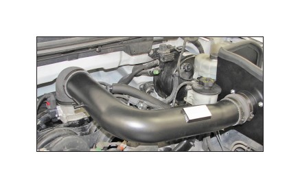
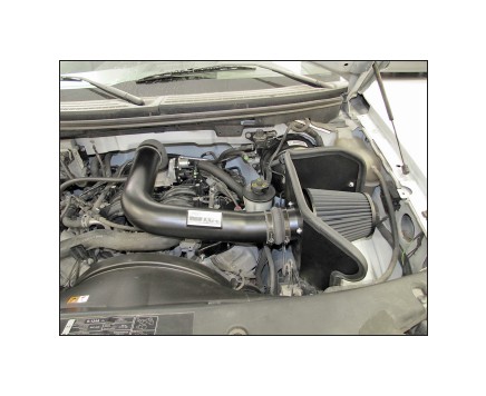
20. Install the K&N® intake tube into the 90° elbow hose and then into the hump hose, align for best fit and then secure with the provided hose clamp. NOTE: On vehicles equipped a Brake Booster/EVAP vent line, it will be necessary to align the vent line to the tube and mark the tube to be drilled. Remove the tube and drill a 5/8”id hole in the marked location and install the provided grommet, be sure to remove any burrs and shavings.
21. Reattach the heater hose and wiring harness to the studs installed in the previous step.
22. Install the provided crank case vent hose onto the vent port on the K&N® intake tube and then onto the vent on the valve cover.
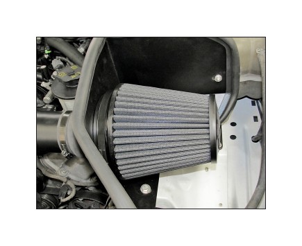
23. Install the K&N® air filter onto the filter adapter and secure with the provided hose clamp.
24. Reconnect the mass air sensor electrical connection.
25. Reconnect the vehicle’s negative battery cable. Double check to make sure everything is tight and properly positioned before starting the vehicle.
26. It will be necessary for all K&N® high flow intake systems to be checked periodically for realignment, clearance and tightening of all connections. Failure to follow the above instructions or proper maintenance may void warranty.
ROAD TESTING:
1. Start the engine with the transmission in neutral or park, and the parking brake engaged. Listen for air leaks or odd noises. For air leaks secure hoses and connections. For odd noises, find cause and repair before proceeding. This kit will function identically to the factory system except for being louder and much more responsive.
2. Test drive the vehicle. Listen for odd noises or rattles and fix as necessary.
3. If road test is fine, you can now enjoy the added power and performance from your kit.
4. K&N Engineering, Inc., requires cleaning the Blackhawk InductionTM intake system’s air filter element every 100,000 miles. When used in dusty or off-road environments, our filters will require cleaning more often. We recommend that you visually inspect your filter once every 25,000 miles to determine if the screen is still visible. When the screen is no longer visible some place on the filter element, it is time to clean it. To clean, purchase our Synthetic Filter Cleaner, part number 99-0624 and follow the easy instructions.
