 FREE 1 to 3-Day Delivery on Orders $119+ Details
How to Install PIAA 6 in. RF Series LED Light Bar - Fog Beam (97-18 All) on your Ford F-150
Thank you very much for purchasing PIAA product. Read this instruction manual thoroughly for proper use of the product. After completing your installation, please keep this manual for future reference.
Please read the cautionary points before installation to ensure safe utilization of the product.
WARNING:
● The lamp becomes very hot when turned on. When parking your car near flammable items such as dried leaves, turn off the lamp as it may cause a fire.
● Do not look directly into the light for long periods. Doing so may cause eye irritation or visual impairment.
CAUTION:
● The lamp and the switch harness are intended for automobile use. Do not use for any other purpose.
● This lamp is intended for use in rain (day or night), during foggy or snowy conditions where visibility is hampered. Do not use during normal driving conditions.
● Do not operate the switch while driving.
● If the lamp is kept on when the engine is not running, it may drain the battery.
● Make sure the lamp is installed securely before driving the vehicle. If a problem is found, fix it immediately.
● Check for any loose screws that hold the lamp in place before driving. If you find any loose screws or bolts (if a bracket is used), tighten them securely. If you notice a loose part while driving, inspect the section immediately and make the necessary adjustments.
● Avoid repeatedly turning the lamp off and on as it may reduce the overall life of the LED.
● Some vehicles produce a high voltage electric charge when the engine is started. Avoid loading extra voltage to lamps by turning the switch off when you start engine.
● Avoid needless disassembly of the lamp or the switch harness as it may cause it to fail.
● If the lamp and/or the switch harness is removed and set aside for safekeeping, wipe away all dust or grime and store in a place free of moisture.
● If the lens is cracked or damaged in any way, verify whether there is any damage to the harness. If there is any damage to the cord covering, replace it immediately.
● Avoid injury when replacing the harness and the switch harness. Please dispose of it as a non-combustible item.
Please read the installation procedures thoroughly beforehand.
● In order for the lamp to perform at its full potential, use the relay harnesses manufactured by PIAA.
● All work procedures should be carried out in a location with adequate space. Place the shift lever in neutral or in the parking position. Turn off the engine and set the parking brake.
● Make sure the engine compartment is adequately cool before starting work. Do not begin work if engine parts such as radiator, oil-cooler or turbo parts are still hot.
● Do not add additional holes to the main body of the lamp. Also, do not apply adhesives or stickers to the lamp parts.
● Do not modify the lamp harness or the switch harness in any way. Such modifications may cause it to overheat or short. In some cases, it may cause the vehicle to catch fire. PIAA will not be liable for damage caused by such modifications.
● When removing the battery terminals, do not touch the (-) and ( ) terminals simultaneously. An electrical shock may occur. Wear rubber gloves when carrying out such work procedures.
● Make sure the (-) and ( ) terminals do not make contact with metal. It can be extremely dangerous if a short occurs.
● Make sure all bolts are tightly secure. If there are any loose bolts tighten them accordingly.
● After installing the lamp, adjust the lamp so the beam shines at least 40m in front of the vehicle. Also, adjust the lamp a little toward the left so that it does not shine directly into the eyes of the opposing driver of a vehicle. (as traffic laws stipulate - refer to p.6 for adjustment procedures)
● After installing the lamp, make sure the headlamps, wipers and horn are working normally.
● When the battery terminal is removed, memory related to the clock, radio, audio system etc, will be affected. After all work procedures are completed, reset to the original settings. (For adjustment procedures refer to your car's instruction manual)
Caution Regarding Wiring / Please read thoroughly
WARNING:
● When installing the wiring harness, strictly follow the cautionary points mentioned below. Incorrect or faulty wiring may cause the lamp to operate improperly. In some cases, it may cause the vehicle to catch fire.
CAUTION:
● Before you begin always remove the (-) and ( ) terminals. Always remove the (-) terminal first and make sure a short does not occur.
● When removing the battery terminals, always turn the key to OFF and remove it. Turn all other electrical units off such as the light switch.
● When removing the battery terminals, if a cord (for an electrical unit) is connected, wind a length of vinyl tape around the (-) and ( ) terminals to clearly identify them.
● Verify the ( ) terminal (white) and earth (black) before connecting.
● Do not obtain ( ) voltage from the alternator.
● Obtain the ( ) current necessary for the switch from the ( ) current used for the light switch. (Do not use the same current used for a computer, radio or audio system)
● Install the switch harness in a position where it will not make contact with high temperature surfaces such as the engine, radiator or engine compartment.
● Arrange the switch harness so that it does not make contact with moving parts.
● Do not place the switch harness on high-voltage wires such as brake or air-conditioning wires.
● If the switch harness makes contact with a part of the engine, apply a length of ordinary cushioned tape around the harness.
● When connecting the connector, insert until you hear an audible“ click”
● When removing the connector, hold the main body of the connector and pull it out. If excess force is used to pull the cord, it may damage the connection, which could cause it to overheat.
● Make sure the harness does not sag. Use a harness band of vinyl tape to secure it in place to wiring inside the engine compartment.
● Before connecting it to the battery, verify the wiring arrangement.
● When connecting the battery terminal and or other electrical units, do not mistake the (-) and ( ) terminals. Always start with the ( ) terminal.
● After all wiring is complete, confirm that it works properly. If it fails to activate, refer to“【4】Troubleshooting”section of this manual.
Before starting the work procedures...
※ The following work procedures shown below are for the "RF6" model but the same procedures can also be used for units "RF10" and "RF18".
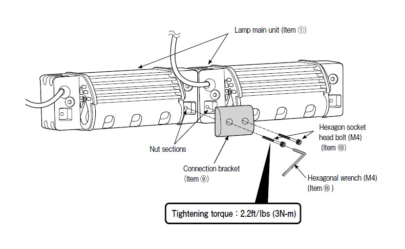
By using the Connection bracket (Item ⑨ ) 2 main lamp units (Item ① ) can be connected. When installing and using the main lamp unit, follow the ■ Lamp connection procedures indicated below. If not installing the main lamp unit using this procedure continue on to page 5, [1] Installation preparations and follow the instructions indicated there. In addition, if not connecting the lamps, the Connection brackets (Item ⑨ ) and the Hexagon socket head bolt (M4/Item ⑩ ) will not be used. Therefore, please store them properly for safekeeping.
■ Lamp connection procedures
Install the Connection bracket (Item ⑨ ) to the nut on the lamp main unit as shown in the figure. Use the Hexagon socket head bolt (M4/Item ⑩ ) to secure it firmly in place.
CAUTION
● Use the recommended torque and apply equal force when tightening the Hexagon socket head bolt (M4/Item ⑩ ).
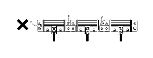
● Do not install more than 3 lamp main units.
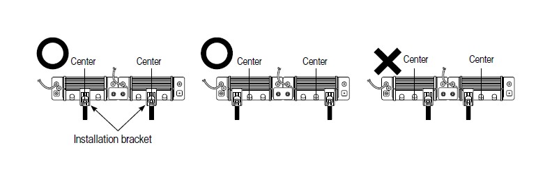
● When connecting lamp units“ RF6” and“ RF10”, we recommend that 2 Installation brackets (Item ②) be used on each lamp unit.
If there is a problem with the installation position and only one Installation bracket can be installed on each lamp, install it on the outer hole from center.
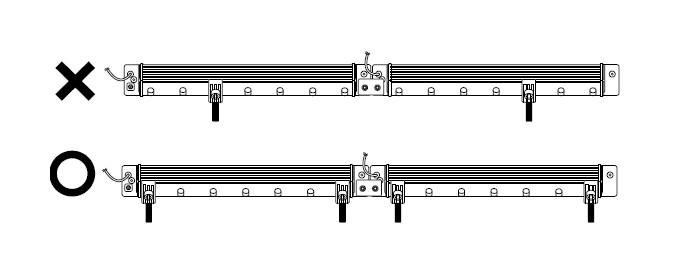
● When installing and using the“ RF18” unit, make sure to install 2 Installation brackets (Item ②) at 2 positions on each lamp.
1. Installation preparations
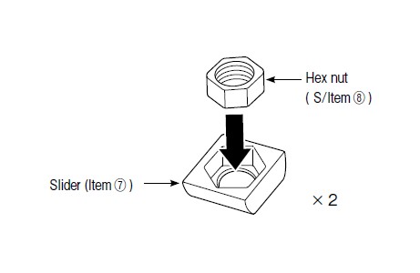
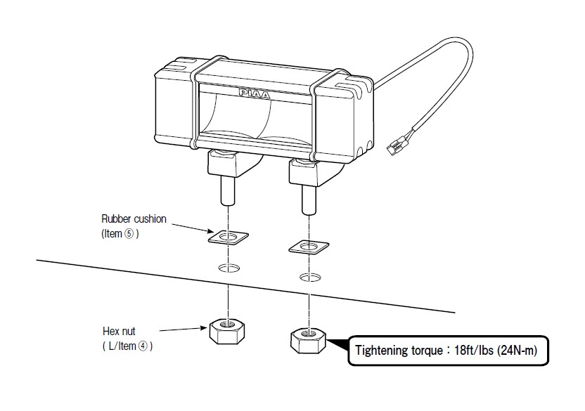
(1)Combine the Slider (Item ⑦ ) and the Hex nut ( S/Item ⑧ ) as shown in the figure below.
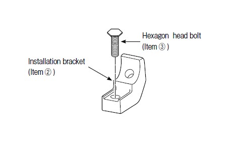
(2)Combine the Installation bracket (Item ② ) and the Hexagon head bolt (Item ③ ) as shown in the figure below.
CAUTION:
● If installing the lamp main units“ RF10 and “RF18” to the vehicles without combining them, make sure to install 2 Installation brackets on 2 positions on the lamp main unit. With unit“ RF6”, one Installation bracket can be used in the center but we recommend installing them on 2 positions.
(3)Take 2 sets made up of the Hex nut and Slider assembly that was combined in (1) put them into the lamp main unit positions as indicated in the figure. Be careful not to drop the Hex bolt out of the Slider.
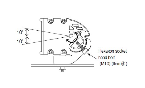
(4)Take 2 sets made up of the Hex nut and bracket assembly that was combined in (2) and using the Hexagon socket head bolt (M10/Item ⑥ ), screw it firmly in place.
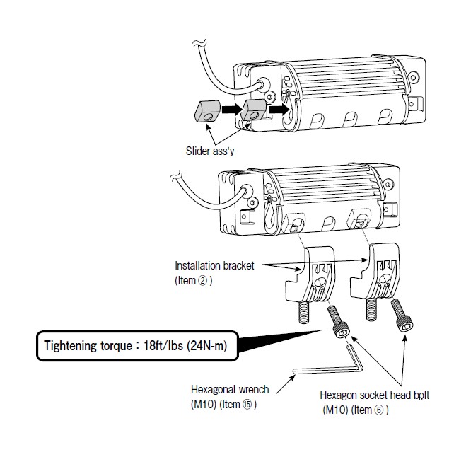
Advice
● After the lamps are installed on the vehicle, the Hexagon socket head bolts (M10/Item ⑥ ) can be loosed and the angle of the lamp can be adjusted.
2. Lamp installation
For lamp installation, a hole with a diameter of 10mm is required. Make necessary preparation such as installation of lamp bracket.
CAUTION:
● When using a commercially supplied lamp bracket, before removing the bolt that is already installed on the car body, make sure that it is safe to do so.
● The lamp should be mounted in an area sufficient to support its size and weight. Failure to do so may result in excess vibration leading to shorter bulb life and or physical damage to the lamp or your vehicle.
● Do not attempt to install the lamp directly to any plastic part of the car body. If the lamp needs to be installed on the plastic reinforcement materials should be placed on both sides of the plastic part.
● When installing, make sure the lamp body, lens and rim are not touching the bumper and other plastic parts. Such plastic parts might deform.
● The lamp installation surface should be flat.
● The lamp should be tightened to the degree that the lamp body cannot be moved by hand.
● The lamps are designed to be mounted upright. It is very important that you make sure that the“ PIAA” etched in the lens reads right side up.
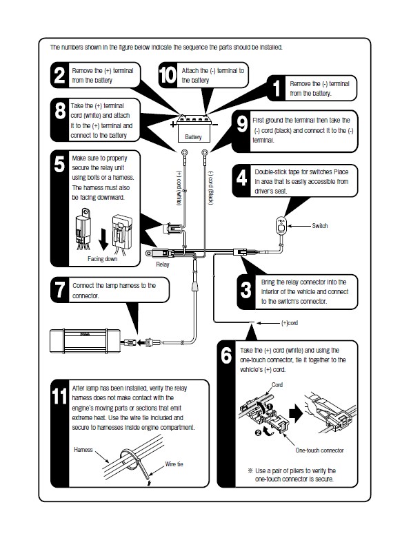
3. Relay Harness Installation Sequence
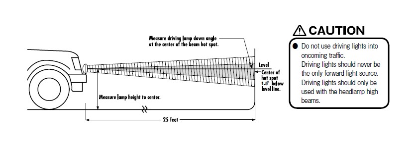
DRIVING / Spot Light Aiming
Typically, driving lights are mounted above the front bumper about 30 inches from the ground to provide extra high beam illumination. Driving lights can be mounted below the bumper, although they will not be as effective because the light will hit the ground sooner and reduce the range of the light.
Visual aim is made with the center of the beam hot spot 1.5 inches below the lamp center at 25feet with the lamp facing straight forward. (see below.)
4. Troubleshooting……Verify each section according to the following.
1. After installation, if the lamp does not activate
→ Check the wiring and make sure there are no faulty or irregular connections .
● If the switch illumination does not light up.
→ Verify the ( ) wire from the switch is properly connected. If it is not correctly connected it will not activate.
→ Verify the fuse located on the vehicle's wiring system. (the switch's ( ) wire should be connected to the fuse box). If it is burned out, connect it to another circuit.
→ If the switch itself is faulty, the same symptoms may exist. We recommend that the entire switch unit be replaced.
→ Check the fuse for the switch harness. If it is burned out, follow instructions indicated in [ 3 Fuse replacement Procedures].
● The switch illumination lights up but when operating does not work.
→ Check the connecting (-) cord to the body earth.
→ There may be cases where each terminal related to specific sections may be incorrectly connected. Check for any lose wires and also for dirt or grime.
→ Check the switch operation If an abnormality is found, replace it accordingly.
2. If the LED suddenly fails to light up …
→ Check the fuse located on the vehicle's wiring system. If it is burned out, replace accordingly.
→ Check the fuse for the switch harness. If it is burned out, follow instructions indicated in [ 3 Fuse replacement Procedures].
→ There may be cases where each terminal related to specific sections may be incorrectly connected. Check for any lose wires and also for dirt or grime.
→ Check the switch operation if an abnormality is found, replace it accordingly.
3. Fuse replacement procedures
→ A short circuit may have occurred. Check the wiring system. If any type of damage is found replace accordingly. (Non-replacement may pose a potential danger) (Short circuits are mainly caused when wires are caught in the assembly or when there is a gap in the sleeve connected to the lamp harness).
