 FREE 1 to 3-Day Delivery on Orders $119+ Details
How to Install ReadyLIFT 7 in. Off Road Lift Kit w/ SST3000 Shocks - Black on your F-150
Shop Parts in this Guide
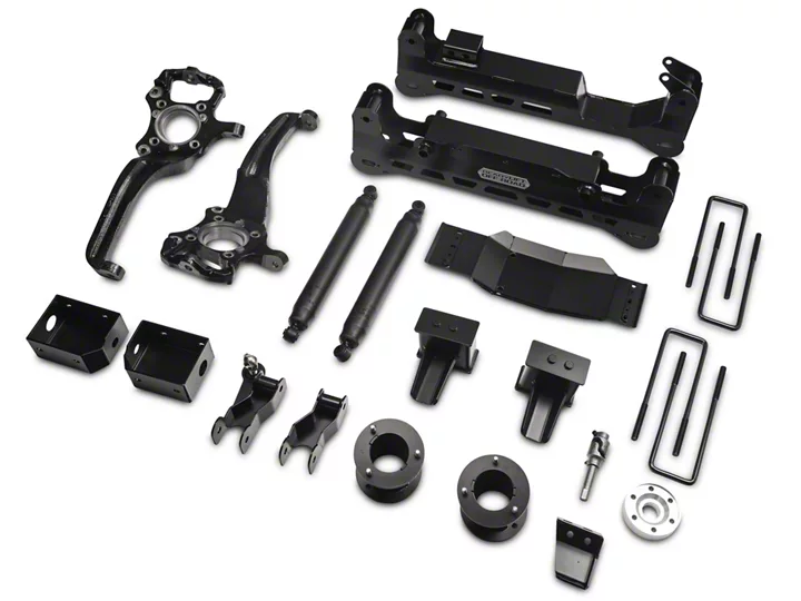
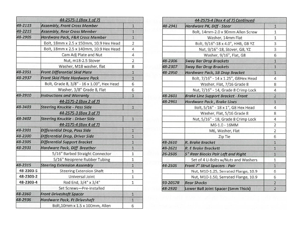
Installation Instructions 7" Lift Kit 2015 F150 4WD ONLY(44-2575)
Bill of Materials
Safety Warning
Before you start installation:
ReadyLIFT® Off Road Suspension highly recommends that the installation of this product be performed by a professional mechanic with experience working on and installing suspension products. Professional knowledge and skill will typically yield the best installation results. If you need an in- staller in your area, please contact ReadyLIFT® Suspension customer service to find one of our "Pro-Grade" Dealers. Notes:
• Installation by a professional mechanic is highly recommended.
• A Factory Ford Service Manual for your specific Year / Make / Model is highly recommended for reference during installation.
• Installation requires cutting and welding of the vehicle frame.
• Vehicles with a two piece rear driveline may require a carrier bearing drop support bracket, call technical assistance for details.
• Vehicles achieving more than 5" of rear lift may require rear driveline modifications, call technical assistance for details.
• All lifted vehicles may require additional driveline modifications and or balancing.
• A four wheel vehicle alignment will need to be performed after installation of this product.
• Speedometer / Computer recalibration is required if changing /- 10% from factory tire diameter.
• Use of a Vehicle Hoist will greatly reduce installation time. Vehicle must be in excellent operating condition.
• Repair or replace any and all worn or damaged components prior to installation.
Place the vehicle on level ground. Engage the parking brake and block the rear wheels for safety.
Record stock vehicle ride height measurements on both the front and the rear, this will provide and guideline on vehicle rake and lift height. Measure from the center of the wheel up to the bottom edge of the fender well opening and record on chart provided on page 2.
Disconnect the vehicle power source at the ground terminal on the battery using a 10mm socket.
***2011 and newer models equipped with EPAS (Electronic Power Assist Steering), disconnect the power steering control module connector to avoid arching of the contacts in the internal power relay during disas-sembly and reassembly***
You must Lock Steering Wheel in straight forward position with the column lock or steering wheel locking device.
***Rotating the steering wheel while disconnected from the
vehicle rack & pinion WILL cause damage to the steering column and /or internal clock spring.***
1. Raise the front of the vehicle and support with jack stands at each frame rail behind the lower control arms. Remove the front wheels using a 13/16" socket.
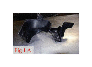
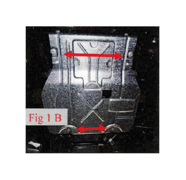
2. Remove all factory skid plates and hardware using 13mm socket. Remove the plastic guard in between the two cross members of the frame by unclipping the plastic clips. Discard all.
(Fig 1 A, B)
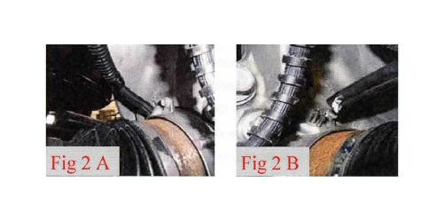
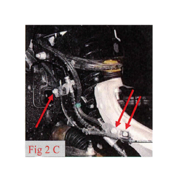
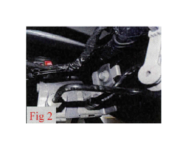
3. Remove the brake line brackets from the knuckle and frame using a 10mm. Remove the ABS line from the knuckle using a 8mm socket. Disconnect the vacuum line from the actuator on the backside of the knuckle. Repeat for driver and passenger sides. (Fig 2 A, B, C)
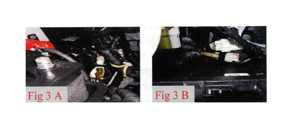
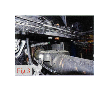
4. Disconnect the ABS wires from the engine compartment and remove from brake line brack-ets. Unclip electrical connectors from plastic holders to gain slack for reassembly later. (Fig 3 A, B)
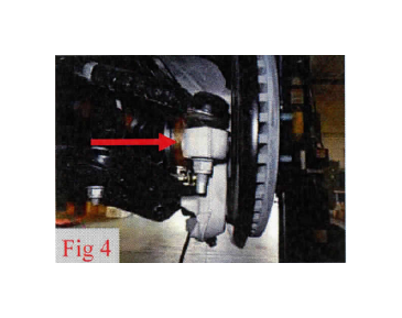
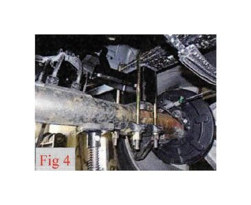
5. Remove the tie rods from the knuckle using a 21mm socket. Strike the tie rod boss on the knuckle with a dead blow hammer to dislodge the taper from the knuckle.
(Fig 4)
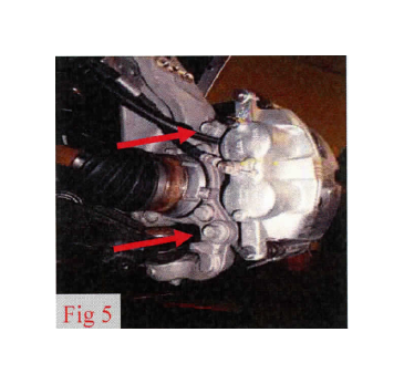
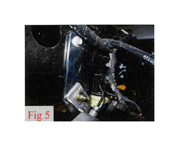
6. Remove the brake caliper anchor bracket bolts using a 21mm socket. Remove the caliper from the knuckle and hang the out of the way using a S - Hook or suitable strap. DO NOT let the caliper hang by the brake hose.
(Fig 5)
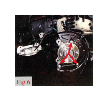
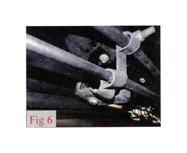
7. Remove the brake rotor and dust shield using an 8mm socket. (Fig 6)
8. Remove the axle nut dust cover. Then remove the axle nut using a 15mm socket. (Fig 7 A, B)
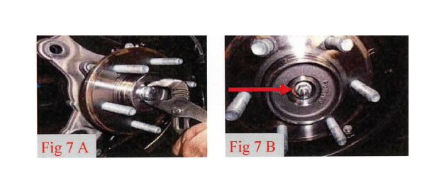
Repeat for driver and passenger side
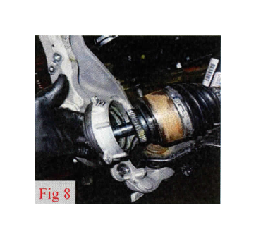
9. Loosen the upper ball joint nut using an 18mm socket. Strike the ball joint boss on the knuckle with a dead blow ham-mer to dislodge the taper. Remove the upper ball joint nut and separate the upper control arm ball joint from the knuckle. Us-ing a 8mm socket remove the hardware holding the vacuum actuator on the knuckle and slide it and the axle off to the side. Carefully remove the vacuum hub from the axle. USE CAU-TION TO NOT DAMAGE THE VACUUM ACTUATOR. Loosen the lower ball joint nut using a 21mm socket. Strike the ball joint boss on the knuckle with a dead blow hammer to dislodge the taper and slide the knuckle off of the ball joint. (Fig 8)
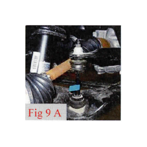
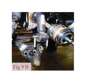
10. Remove the sway bar end link and strut from the lower
control arm using 18mm socket.
(Fig 9 A, B)
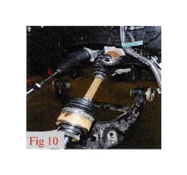
11. Remove the lower control arms using a 27mm socket and
21mm wrench.
(Fig 10)
Repeat for driver and passenger side
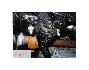
13. Remove the sway bar from the frame using a 15mm socket. (Fig 12)
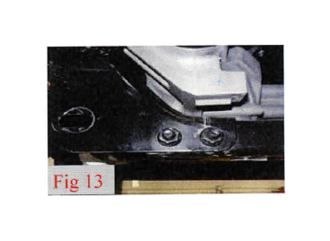
14. Remove the rear cross member from the frame using a 18mm socket and 15mm wrench. Discard cross member and driver side hardware. They will not be reused. Save passenger side hardware. (Fig 13)
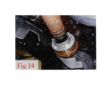
15. Mark driveshaft to differential location for reinstall later. (Fig 14)
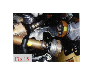
16. Remove the driveshaft mounting bolts using a 10mm socket. Re-move from the front differential. Allow the driveshaft to rest out of the way.
(Fig 15)
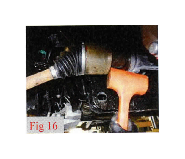
17. Remove both the driver side and passenger side CV axle. Strike the shaft with a mallet or soft hammer to dislodge it from the c-clip. This step makes handling the differential much easier, but is not nec-essary.
(Fig 16)
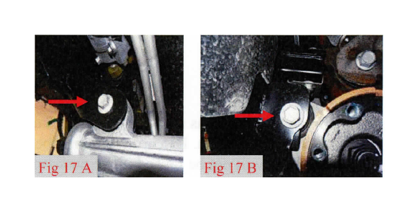
***Warning: The front differential is heavy and awkward. It is best removed by two people. Do not tilt the differential towards the opening on the driver side as gear oil will spill out.***
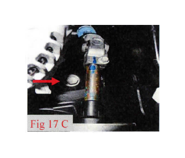
18. Support the differential with a suitable jack. Remove the vent tube. Remove the 3 differen- tial mounting bolts from the frame using a 18mm socket and lower differential out of vehicle. (Fig 17 A, B, C)
19. Locate the rack & pinion coupler pinch bolt. Mark the alignment of the rack and pinion input shaft and the coupler. Remove the pinch bolt using a 10mm socket and separate.
(Fig 17 C)
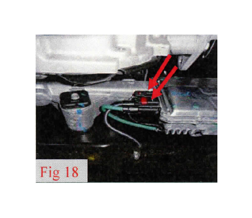
20. Disconnect the electrical leads to the rack and pinion. (Fig 18)
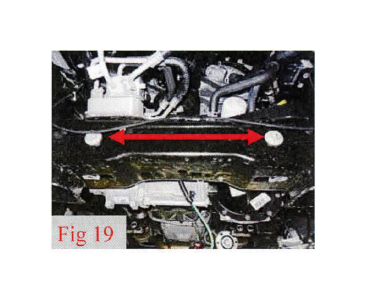
21. With the rack supported, locate the two large bolts that hold the rack & pinion to the vehicle frame and remove using a 21mm and 24mm socket. Carefully lower the rack & pinion assembly from the vehicle.
(Fig 19)
Front Installation
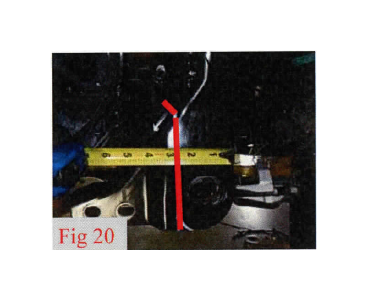
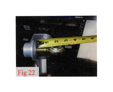
22. The driver's side rear lower control arm frame pocket must be modified to provide clearance for the differential in its relocated po-sition. On the front and back side of the frame pocket measure from the outside edge 2 5/8". Mark a vertical cut line at the mark, all the way to the bottom. Connect the 2 lines across the top of the pocket. Using a suitable cutting tool, cut this pocket off the frame. Sand and paint exposed metal with quality rust preventative paint.
(Fig 20)
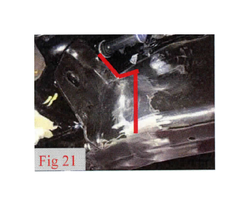
23. Locate the upper differential frame mount. Mark a line across the center of the mount. Make a cut to the frame. Cut the front half off the frame and sand flush with the frame. Paint exposed metal with quality rust preventative paint. This cut is for clearance of the steer-ing shaft extension and u-joint.
(Fig 21)
http://lib.americanmuscle.com/files/contentgenerator/readylift-7-inch-offroad-blk-2015-manu-install.html/readylift-7-in.-off-road-lift-kit-w-sst3000-shocks-black-on-your-f-150-29.png
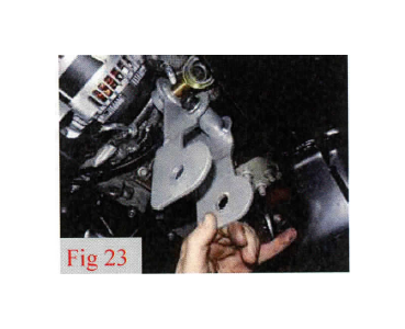
25. Install the completed driver side drop bracket into the factory lo-cation using the 14mm x 90mm Allen bolt and flat washer from bag (48-2941). Do not tighten at this time.
(Fig 23)
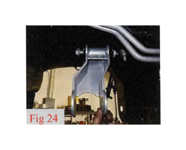
26. Locate passenger side differential drop bracket 48-2301 and in-stall into the factory location using factory bolt and capture nut. Do not tighten at this time.
(Fig 24)
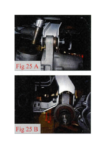
27. Install differential onto the drop brackets using 2, 9/16" x 4" bolts, and 2 washers from bag 48-2941 from the front of the vehicle facing the rear. Do not install the 2nd washer and nut at this time. Rack and pinion shown for illustration purposes. Install vent tube ex-tension from bag 48-2931 onto vent tube and differential.
(Fig 25 A, B)
28. Locate passenger side differential brace 48-2305 and install onto passenger differential drop bracket. Install the 9/16" 2nd washers and c-nuts from bag 48-2941 onto both driver and passenger side drop bolts. Do not tighten at this time.
(Fig 25 B)
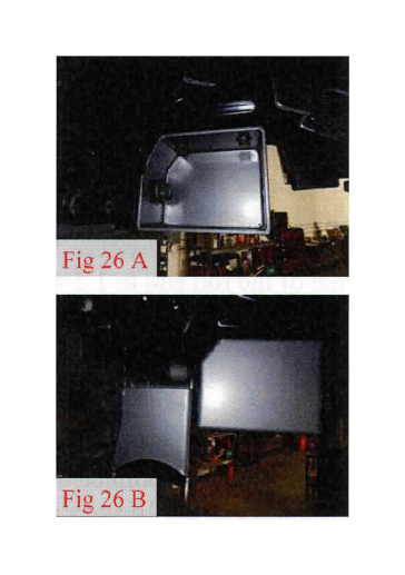
29. Locate the sway bar drop brackets, driver side 48-2306 and pas-senger side 48-2307. Install brackets to corresponding sides of the frame using 7/16" x 1 1/4" bolts, flat washers, and c-nuts from bag 48-2950. Do not tighten at this time.
(Fig 26 A, B)
30. Locate rear cross member 48-2215 and install into the factory control arm frame pockets using 18mm x 150mm bolts, flat washers, and c-nuts from bag 48-2905. Go through the sway bar drop brackets and then the factory control arm frame pockets from the rear of the vehicle. Do not tighten at this time.
(Fig 26 A, B)
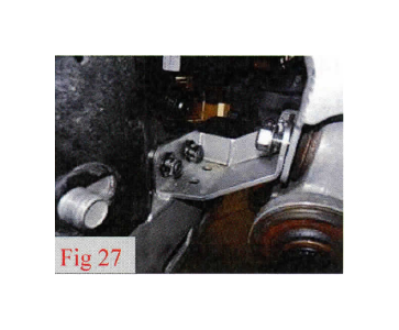
31. Install factory rear cross member bolts and nuts into the passen-ger side frame pocket and into passenger differential support bracket 48-2305. Do not tighten at this time.
(Fig 27)
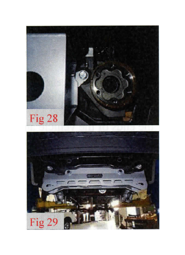
32. Install rear differential mount using 9/16" x 4" bolt, flat washers,
and c-nut from bag 48-2941. Do not tighten at this time.
(Fig 28)
33. Locate and install front cross member 48-2115 using the factory control arm bolts and nuts from the rear of the vehicle facing for-ward. Do not tighten at this time.
(Fig 29)
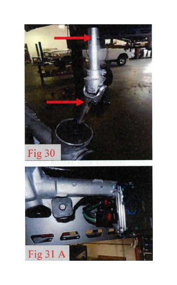
34. Locate the steering u-joint assembly 48-2303-2,48-2303-5. In-stall the complete assembly onto the rack and pinion. Torque the u-joint Allen pinch bolt to 165 in-lbs.
(Fig 30)
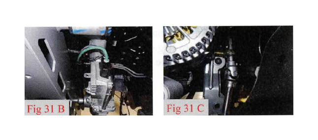
35. Install the rack and pinion unit onto the front cross member us-ing the factory bolts, lining up the steering extension through the 3/4" rod end. Attach factory intermediate shaft to extension using factory pinch bolt and 10mm socket. Use a drop of Loctite on pinch bolt. Torque to 165 in-lbs. Plug electrical connectors into rack and pinion. Front differential not shown for picture taking purposes. Do not tighten main bolts at this time. (Fig 31 A, B, C)
36. Install driver and passenger axles at this time if removed by slid-ing them together with the differential until c-clip engages.
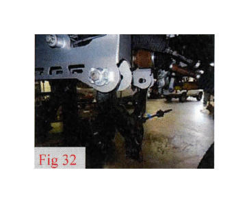
37. Install driver and passenger side lower control arms into corre-sponding sides of the cross members using 18mm x 140mm, flat washer, cam bracket and cam nut from bag 48-2905. Bolts facing to the ends of the vehicle and cam plates on the outside of the cross member. Do not tighten at this time.
(Fig 32)
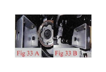
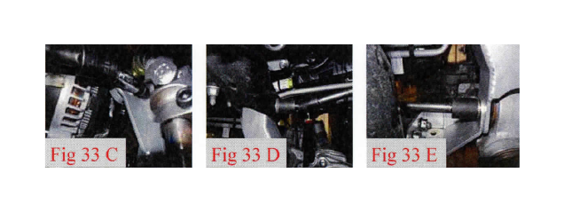
38. Tighten all differential, rack and pinion, and cross member hard-ware at this time using 12mm Allen head tool, 5/8", 11/16", 15, 18, 21, 22, 24, 27mm sockets and wrenches. Starting with differential, torque all differential including the differential support to cross mem-ber hardware to 95 ft-lbs, torque the cross member main hardware to 240 ft-lbs, torque sway bar drop bracket hardware to 60 ft-lbs, torque the rack and pinion to front cross member hardware to 150 ft-lbs. (Fig 33 A, B, C, D, E)
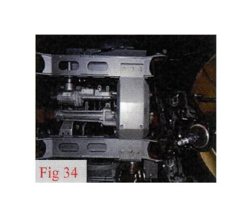
39. Install the front skid plate 48-2351 using 3/8" x 1" hardware
from bag 48-2937 and 9/16" socket. Torque to 35 ft-lbs.
(Fig 34)
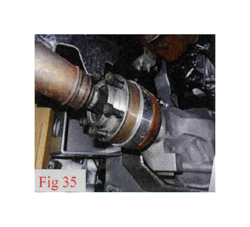
40. Install driveshaft spacer 48-2360 and driveshaft in the same ori-entation with the marks made in step 15 using the 10mm x 100mm Allen head bolts from bag 48-2936 and 8mm Allen head tool. Apply Loctite to all bolts. Torque hardware to 76 ft-lbs.
(Fig 35)
Repeat for driver and passenger sides
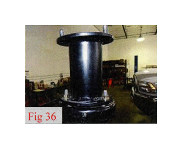
50. Install the driver and passenger side strut spacers 44-2507 to their corresponding struts using supplied 10mm x 1.50 flange nuts and 14mm socket. They are marked D for drivers and P for passen-ger. Torque to 35 ft-lbs.
(Fig 36)
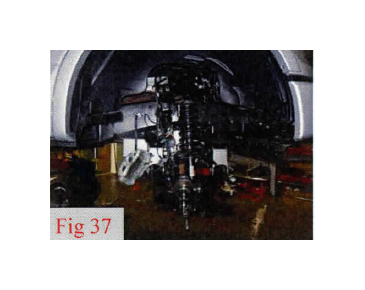
51. Install completed strut assemblies into vehicle frame and lower control arms in their corresponding locations using supplied 10mm x 1.25 flange nuts from 44-2507, factory lower hardware and 14, 18mm sockets. Torque upper nuts to 35 ft-lbs and lower nuts to 150 ft-lbs.
(Fig 37)
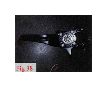
52. Locate driver knuckle 48-2402 and factory driver knuckle. Re-move hub assembly using an 18mm socket. Inspect the mounting surface for any corrosion or dirt and clean as necessary. Install to af-termarket knuckle in the same orientation using factory hardware. Torque to 148 ft-lbs. Repeat procedure for the passenger knuckle 48-2403.
(Fig 38)
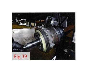
53. Locate the vacuum hub assembly and place onto the factory
axle.
(Fig 39)
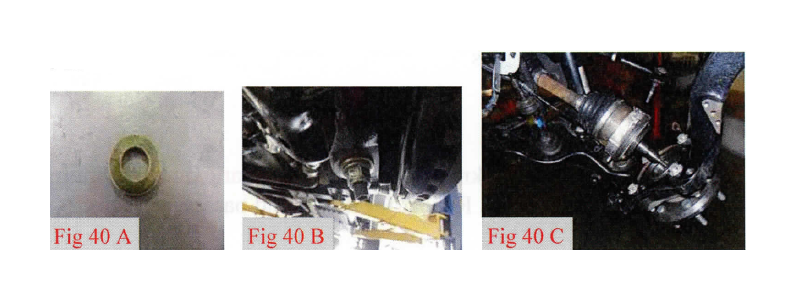
54. Install new knuckles onto the lower ball joints using factory ball joint nut, 3/4" thick washer from bag 48-2920 and 21mm socket. Run tight at this time. Will torque in later step.
(Fig 40 A, B, C)
*** Important*** Read and understand following steps. Failure to do so may result in broken or damaged vacuum actuator.*** Repeat for driver and passenger side
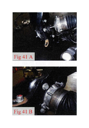
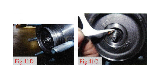
55. Raise knuckle towards upper control arm while guiding the axle shaft into the hub assembly. Take vacuum actuator and move to knuckle mounting surface making sure to engage the splined inner ring to the hub assembly and that the vacuum ports are pointing to the top of the knuckle. Once engaged to splines, install upper ball joint to knuckle using factory ball joint nut. Leave loose at this time. Install vacuum actuator using factory hardware and 8mm socket. Torque to 5 ft-lbs. Grab axle and pull towards the hub assembly while rotating the hub to engage the splines of the axle with the vac-uum actuator. Once the splines have been engaged, install factory axle nut using 15mmsocket. Torque to 18 ft-lbs. You will be able to tell if the axle has been fully engaged to vacuum actuator and hub as-sembly when the shoulder of the axle is visible through the hub and when rotating hub assembly the axle will rotate also. The shoulder should be 2mm under the nut mounting surface. If this is not the case, then the hub assembly will need to be rotated more until full engagement of splines. These steps are very important to follow. The vacuum actuator is made of plastic and is very easily damaged. Re-peat steps for driver and passenger sides. (Fig 41 A, B, C, D)
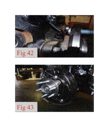
56. Install the ABS sensor onto the hub assembly using factory Allen bolt hardware and 5mm Allen tool. Torque to 5 ft-lbs. Repeat for driver and passenger sides
(Fig 42)
57. Install dust shield to knuckle using factory hardware and 8mm socket. Torque to 5 ft-lbs. Repeat for driver and passenger sides. (Fig 43)
Repeat for driver and passenger side
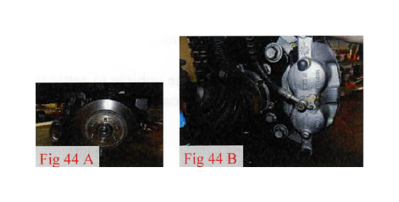
58. Install rotor and brake caliper assembly to hub assembly and knuckle using factory hardware and 21mm socket. Apply a drop of Loctite to threads and torque to 148 ft-lbs. (Fig 44 A, B)
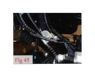
59. Install brake line bracket to knuckle using 6mm x 16mm from bag 48-2961 and 10mm socket. Install ABS wire to knuckle using factory hardware and 8mm socket. Torque all 10 ft-lbs. Install vac-uum lines to vacuum actuator.
(Fig 45)
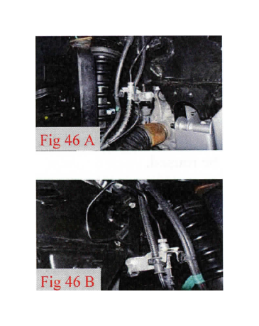
60. Install front brake line drop bracket 48-2601 to factory hard line bracket using 5/16" x 1" bolts, flat washers, and c-nuts from bag 48-2961 and 1/2" socket and wrench. Gently pull down and bend the metal brake line at the frame to be able to attach the brake line drop bracket to the factory location using the factory hardware and 10mm socket. Torque all brake line bolts to 10 ft-lbs.
(Fig 46 A, B)
61. Attach ABS wire to factory locations on factory brake line brack-ets. Run the ABS line on the outside of the strut tower next to the vacuum lines at strut tower location, attach to the frame with a zip tie through the upper control arm pocket. Reattach electrical connectors in engine compartment.
62. Install outer tie rod ends to knuckle using factory hardware and 21mm socket. Torque tie rod end nut and lower ball joint nut to 110 ft-lbs. Torque the upper ball joint nut to 85 ft-lbs.
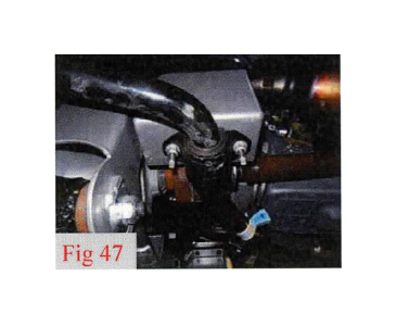
63. Install sway bar to drop brackets using factory hardware and 15mm socket. Torque to 35 ft-lbs. Install end links to lower control arm using factory hardware and 18mm socket. Torque to 40 ft-lbs. (Fig 47)
64. Install the wheels and tires and lower the vehicle to the ground. Torque lug nuts to wheel manufacturer specifications.
65. Jounce the front of the vehicle to settle the front suspension. Move the lower control arm eccentric cams to full inboard. Torque to 150 ft-lbs.
Rear Install
1. Block the front wheels and raise the rear of the vehicle. Place jack stands under the frame rails ahead of the spring hangers.
2. Remove the rear wheels.
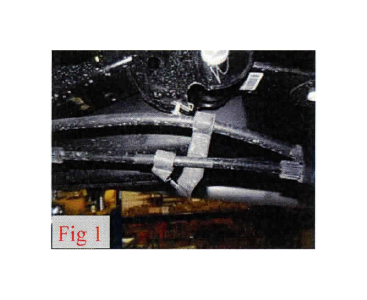
3. Remove the rear emergency brake line bracket from the frame
ahead of the driver side spring using a 8mm socket.
(Fig 1)
4. Remove the brake line bracket from the frame using a 10mm
socket.
(Fig 2)
5. Support rear axle with a suitable jack and remove the shocks us-ing 15mm socket and 18mm wrench. Discard shocks as they will not be reused.
6. Slightly loosen but do not remove the driver side u-bolts. Remove the passenger side u-bolts completely and discard. Lower the axle just enough to remove the factory blocks and install the lift blocks 26-2505. Locate the passenger side lift block, making sure the ta-pered end points to the front and the bump pad is facing the inside of the vehicle. Install the lift block on the axle pad aligning the pins. Raise the axle and the block up to the spring while aligning the cen-ter pins. Install the provided u-bolts, washers and nuts. Snug the u-bolt nuts but do not fully tighten at this time. Repeat steps for driver side.
(Fig 3, 4)
8. Install the rear brake line drop bracket 48-2610 to the frame using factory hardware and 10mm socket. Gently pull the rear hard lines down and attach the rear brake line bracket to the drop bracket using 5/16" x 1" bolt, washers, and c-nut from bag 48-2961. Torque all to 10 ft-lbs.
(Fig 4)
9. Install the rear emergency brake line drop bracket 48-2621 to the frame using the factory hardware and 10mm socket, the emergency brake line bracket to the drop bracket using 5/16" x 1" bolt, washers and c-nut using 1/2" socket and wrench. Torque to 10 ft-lbs.
(Fig 5)
10. Install rear wheels and lower vehicle to the ground. Torque lug nuts to wheel manufacturers specifications.
11. Jounce vehicle to settle suspension. Torque rear u-bolts to 125 ft- lbs.
***Final install and checks***
Recheck that all hardware is of proper torque values and all electrical connections are hooked up. Start vehicle and verify that all dash warning lights are off. Cycle the steering wheel from lock to lock to check for any interference of steering intermediate shaft, steering extension, steering u-joint. wheels, tires, brake lines, hoses, wires, ect and ensure adequate clearance through out the suspension cycle. Adjust as necessary.
* * * Due to manufacturer frame variances, if there is any contact between steering exten-sion, u-joint or intermediate shaft, it may be necessary to remove extension from intermediate shaft and u-joint to adjust rod end in to gain clearance.*** If driving vehicle to an alignment shop, adjust toe prior to vehicle operation.
Install all warning tags and decals as directed:
1. Rear view mirror hanging warning card: Hang from rear view mirror to warn driver of vehi-cle modification.
2. Lifted truck warning decal: Apply decal to the upper left hand corner of the inside of the windshield facing the driver.
Give all installation instructions, warranty information, and all remaining literature to the end user to keep with vehicle records.
