 FREE 1 to 3-Day Delivery on Orders $119+ Details
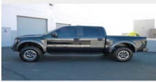
How to Install a ReadyLIFT Front Mid Travel Lift Upgrade Kit on your Ford F-150
Installation Instructions 44-2150
The Bill of Materials represents the component contents of this kit. All hardware is of the highest grade and the components are manufactured to exacting specifications for a trouble free installation. Use the attached torque specifications chart when final tightening of the nut and bolts are done.
1. Put the vehicle on level ground and measure the gap between all of the tires and the fenders.

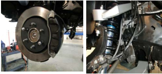
2. Lift the vehicle and remove the wheels.
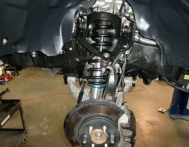
3. Disconnect the ABS line from the fender liner and unplug. Disconnect the ABS line from the other two clips as well.
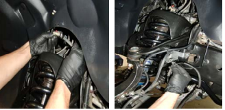
4. Unbolt the brake calipers and hang out of the way.
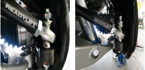
5. Unbolt the sway bar end link from the sway bar.
6. Unbolt the brake line and unhook the vacuum line from the spindle.
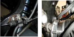
7. Unbolt the tie-rod from the spindle.
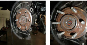
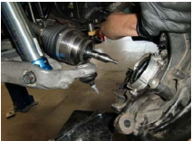
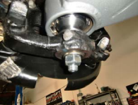
8. Remove the rotor, dust cap and the nut from the axle.
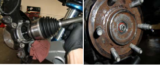
9. Loosen upper control arms (UCA) at frame. Unbolt the UCA from the spindle and move the spindle to allow for the axle to slide out.
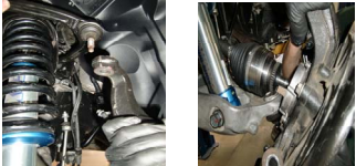
10. Unbolt the spindle from the lower control arm. Remove the spindle.
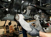
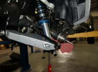
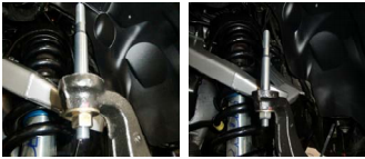
11. Unbolt the shock from the lower control arm, let the arm hang down.
12. Unbolt the shock from the top and remove from the vehicle.
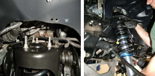
13. Unbolt and remove the upper control arm.
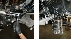
14. Unbolt and remove the lower control arm.
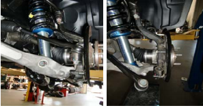
15. Install the ReadyLIFT® lower control arm.
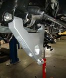
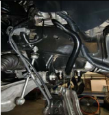
16. Install the ReadyLIFT® upper control arm.
17. Re-install the shock at the top.
18. Install the lower shock into the lower control arm.
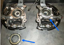
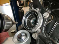
19. Remove the CV joint seal from both of the spindles.
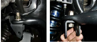
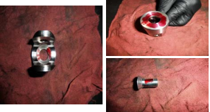
20. Install the misalignment spacers into the LCA uniball. Install the pin with a washer and c-lock nut hand tightened
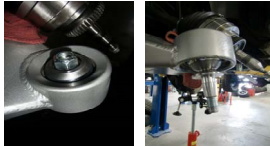
21. Install the spindle onto the LCA. With a washer and a standard nut, tighten the nut down to seat the pin into the spindle.
22. Remove the standard nut and replace with a c-lock nut and tighten.
23. Tighten down the top c-lock nut on the LCA uniball. Then re-install the CV joint seal.
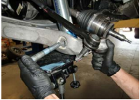
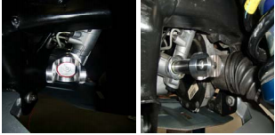
24. Re-install the axle into the spindle. Make sure to line up the teeth. Rotate to ensure that there isn’t anything bound up inside. Re-install the nut and the dust seal on the end of the axle.
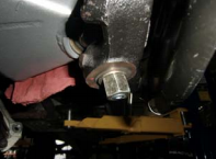
25. Install the tapered pin into the top of the spindle. With a washer and a standard,
nut tighten down the nut to seat the pin in the spindle. Remove the standard nut, replace with a c-lock nut and tighten.
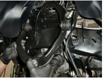
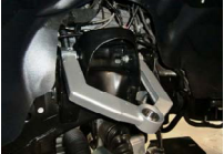
26. Install the misalignment spacers into the UCA uniball and slide down over the pin. Then install the washer and the c-lock nut and tighten.

27. Re-install the rotor and brake calipers. Re-attach the ABS lines, brake lines and vacuum line to the spindle.
28. To use the factory Sway Bar you must purchase Kit # 67-2999. Install new sway bar end link brackets to the sway bar. If not using factory sway bar this would be the time to remove it from vehicle.
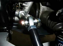
29. Install the sway bar end links to the LCA. Then install the top of the link to the sway bar. If not using Kit # 67-2999 install supplied socket head allen bolt to cap sway bar mount for future use and to protect the thread bung.
30. Install the sway bar end links to the sway bar bracket. Install the nut to the outside of vehicle.
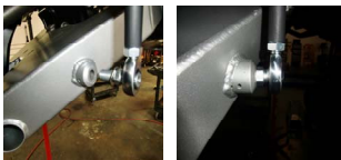
31. Remove the boot from the steering rack. Unscrew the tie-rod from the steering rack.

32. Put red lock-tite on the clevis front and back and on the screw.
33. Install the clevis into the steering rack and align the fork so the opening is vertical.
34. Install the sleeve into the rod end and install the tie-rod into the clevis.
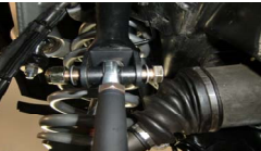
35. Install the pin into the tie-rod mounting hole on the spindle and tighten down using a washer and a standard nut to seat the pin. Replace the standard nut with a c-lock nut.
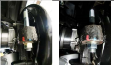
36. Insert the misalignment spacers into the tie-rod and install onto the pin. Use a washer and a c-lock nut and tighten down.
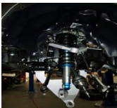
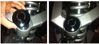
37. Add a small amount of lubricant such as grease to the o-ring on the cap to help seat the cap. To seat cap you may need to tap with rubber mallet.
38. Torque everything down to factory specifications and recheck the installation to ensure it was done properly. Put the tires on the vehicle and set it on the ground. The vehicle must be aligned prior to driving .
Final Checks & Adjustments
Post Installation Warnings: Once the vehicle is lowered to the ground, check all parts which have rubber or urethane components to insure proper torque. Torque wheels to factory specs. Move vehicle backwards and forwards a short distance to allow suspension components to adjust. Turn the front wheels completely left then right and verify adequate tire, wheel, brake line, and ABS wire clearance. Test and inspect steering, brake and suspension components for tightness and proper operation. Inspect
brakes hoses and ABS lines for adequate slack at full extension. Failure to perform the post inspection checks may result in vehicle component damage and/or personal injury or death to driver and/ or passengers. Test drive vehicle and re-check the torque of all fasteners and re-torque wheels on vehicle. Re-adjust headlamps.
Vehicle Handling Warning: Vehicles with larger tires and wheels will handle differently than stock vehicles. Take time to familiarize yourself with the handling of your vehicle.
Wheel Alignment/Headlamp Adjustment:
It is necessary to have a proper and professional wheel alignment performed by a certified alignment technician. Align the vehicle to factory specifications. It is recommended that your vehicle alignment be checked after any off-road driving. In addition to your vehicle alignment, for your safety and others, it is necessary to check and adjust your vehicle headlamps for proper aim and alignment
Vehicle Re-Torque and Safety Inspection:
Upon completion of all services and adjustments performed on your vehicle, and within 50 miles of driving, check to ensure all fasteners and hardware are properly torqued to specification as noted in the vehicles factory service manual or the torque chart included.
