 FREE 1 to 3-Day Delivery on Orders $119+ Details
How to Install RedRock 4x4 3 in. Bull Bar w/ Skid Plate & 20 in. Single Row LED Light Bar - Black (04-17 All, Excluding Raptor) on your Ford F-150
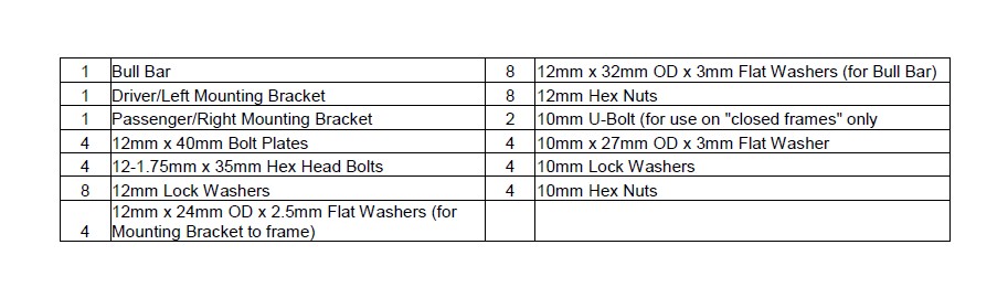
PARTS LIST:
PROCEDURE:
1. REMOVE CONTENTS FROM BOX. VERIFY ALL PARTS ARE PRESENT. READ INSTRUCTIONS CAREFULLY BEFORE STARTING INSTALLATION.
NOTE: It may be necessary to remove/relocate the front license plate and license plate bracket. It is not required, but strongly recommended. If local/state law requires a license plate, license plate relocation kit is available.
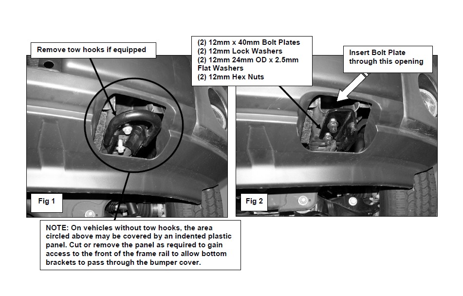
NOTE: It may be necessary to remove the lower plastic portion of the bumper to gain access to the ends of the frame rails. The indented pockets in the lower bumper will need to be cut out to allow the Mounting Brackets to pass through.
2. Vehicles with Factory Tow Hooks
Remove tow hooks by removing the front bolt and only loosening the rear bolt. Slide the tow hooks off. Keep the factory double nut plate in the frame and aligned with the holes.
NOTE: This Bull Bar is not compatible with the factory tow hooks, so you will not be reinstalling the tow hooks.
Position the Mounting Bracket up to the bottom of the frame and secure it with the factory tow hook bolts and factory double nut plate, (Figure 1).
Vehicles without Tow Hooks
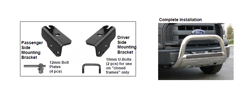
Starting on the driver side of the vehicle, insert (1) 12mm Bolt Plate through the opening in the open front end of the frame and down through the rear hole in the bottom of the frame, (Figure 2). Thread (1) 12mm x 24mm OD x 2.5mm Flat Washer, (1) 12mm Lock Washer and (1) 12mm Hex Nut onto the threaded end of the Bolt Plate. Slide the slotted end of the driver side Mounting Bracket under the nut and washers. Insert the second 12mm Bolt Plate through the remaining hole toward the front of the Mounting Bracket. Secure with (1) 12mm Lock Washer, (1) 12mm x 24 mm OD x 2.5mm Flat Washer and (1) 12mm Hex Nut. Snug but do not tighten the hardware at this time.
Vehicles with "closed ends" on front of frame
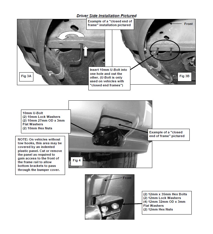
Starting on the driver side of the vehicle, locate the two holes on the bottom of the frame. Insert (1) 10mm U-Bolt into one hole and out the other, (Figure 3A & 3B). Hold the driver side Mounting Bracket in position with the slotted end toward the rear. Secure the Mounting Bracket to the U-Bolt with (2) 10mm x 27mm OD x 3 mm Flat Washers, (2) 10mm Lock Washers and (2) 10mm Hex Nuts, (Figure 4). Snug but do not tighten the hardware.
3. Repeat the appropriate Step 3 for the passenger side Mounting Bracket installation.
4. With help position the Bull Bar on the inside of the Mounting Brackets. Use the included (4) 12mm x 35mm Hex Bolts, (4) 12mm lock Washers, (8) 12mm Flat Washers and (4) 12mm Hex Nuts to attach the Bull Bar to the Mounting Brackets, (Figure 5). Do not tighten at this time.
5. Align and adjust the Bull Bar properly, and tighten all hardware.
6. Do periodic inspections to the installation to make sure that all hardware is secure and tight.
To protect your investment, wax this product after installing. Regular waxing is recommended to add a protective layer over the finish. Do not use any type of polish or wax that may contain abrasives that could damage the finish.
For stainless steel: Aluminum polish may be used to polish small scratches and scuffs on the finish. Mild soap may be used also to clean the Bull Bar.
For gloss black finishes: Mild soap may be used to clean the Bull Bar.
Driver Side Installation Pictured
PROCEDURE:
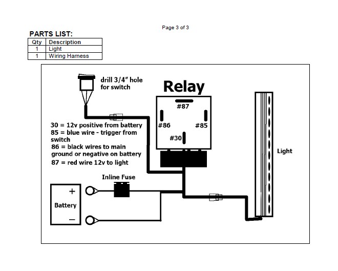
1. REMOVE CONTENTS FROM BOX. VERIFY ALL PARTS ARE PRESENT. READ INSTRUCTIONS CAREFULLY. DRILLING IS REQUIRED. ELECTRICAL KNOWLEDGE IS HIGHLY RECOMMENDED.
2. Install Light into product as instructed. Open hood and disconnect battery.
3. Unwrap preassembled wiring harness. Disconnect the plug in the harness leading to the lighted switch. Locate suitable mounting location for switch. Drill 3/4” hole in panel to mount switch. IMPORTANT: Do not drill any holes in panel until back of location is properly checked for clearance. Use of safety goggles is required.
4. Run switch harness through firewall on vehicle. Drill hole through firewall as required for harness plug. Highly recommend use of rubber grommet (not included) to protect harness. Feed switch harness plug through hole in firewall. Seal firewall with silicone as necessary.
5. Attach Relay and main harness to suitable location near battery (firewall or inner fender for example). Do not connect to battery at this time.
6. Attach switch plug to switch harness and tie harness away from anything that could damage harness.
7. Run the prewired light harness down to the light. Plug harness into prewired plug on light. Tie wiring harness away from anything that could damage harness.
8. Attach the fused red positive and black negative wires on the main harness to the battery. NOTE: Attach black negative wire to negative terminal on battery or suitable chassis ground.
9. Reattach battery cables to battery. Installation is complete.
10. Do periodic inspections to the installation to make sure that all hardware is secure and tight and all wiring harnesses are properly secured and free from excessive movement.
