 FREE 1 to 3-Day Delivery on Orders $119+ Details
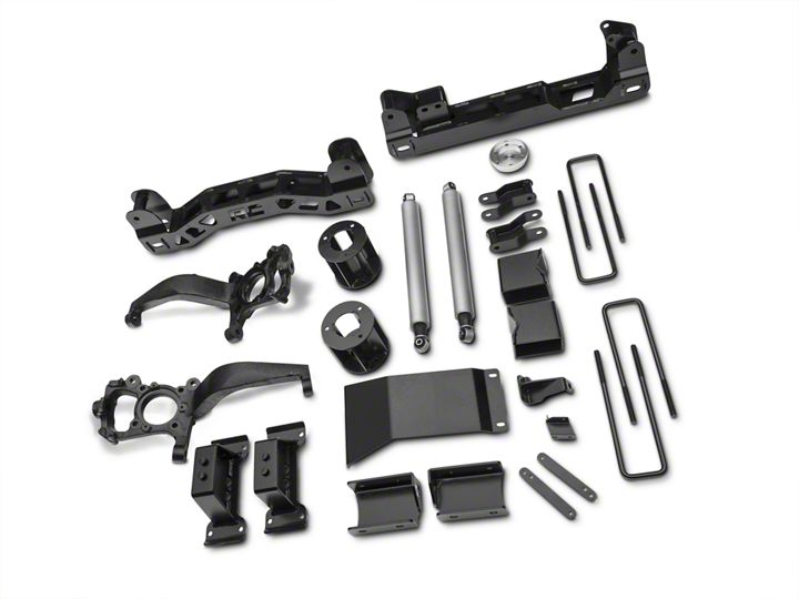
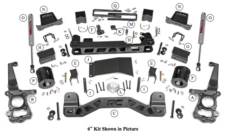
Rough Country 6 in. Suspension Lift Kit (15-16 4WD)
Installation Time
1 days
Tools Required
- 5mm Allen Wrench 8mm Allen Wrench 8mm wrench /socket 10mm wrench /socket 12mm Wrench 13mm wrench / socket 15mm wrench /socket 16mm wrench /socket 18mm wrench /socket 19mm wrench /socket 21mm wrench /socket 22mm wrench /socket 24mm wrench /socket 30mm wrench /socket,
- Floor Jack Jack stands Reciprocating Saw Hammer 9/16 wrench /socket 1 1/16” Wrench Drill 1/4” Drill Bit 5/8” Drill Bit 11/32” Drill Bit 1.25” Hole Saw
Shop Parts in this Guide
Step 1: Chock the rear wheels and jack up the front of the vehicle
Step 2: Place jack stands under the frame rails and lower onto jack stands
Step 3: Remove the wheels/tires using a 21mm socket.
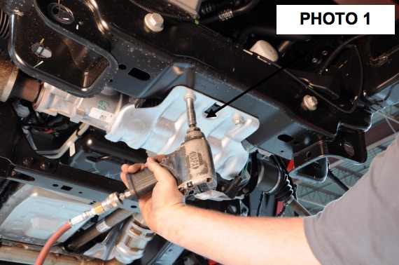
Step 4: Remove the skid plate with a 13mm socket.
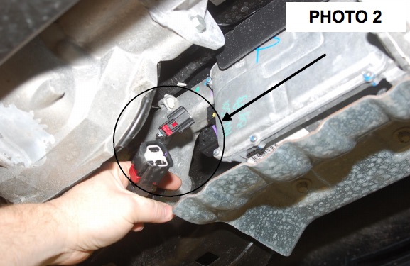
Step 5: Remove the EPAS (Electronic Power Assist Steering) Plugs as shown located on the steering assembly by the front differential.
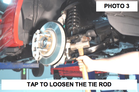
Step 6: Remove tie-rod end using a 21mm wrench. Using the appropriate tool remove the tie-rod from the knuckle.
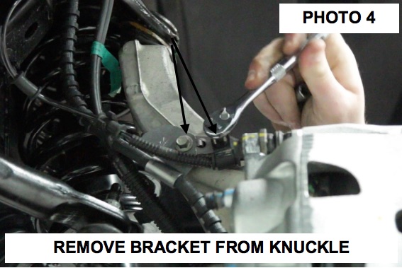
Step 7: Remove the ABS and brake line bracket from the knuckle using a 8mm wrench for the ABS wire and a 10mm wrench for the brake line bracket. Retain hardware for reuse.
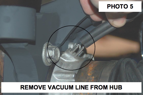
Step 8: Remove the vacuum line from the hub.
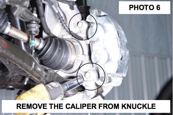
Step 9: Using a 19mm socket & 21mm wrench, remove brake caliper as shown in Photo 6. Hang caliper out of way. Do not let caliper hang by brake hose as this will damage hose. Retain hardware for reuse. Remove rotor.
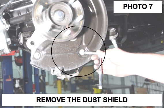
Step 10: Remove the dust shield using a 8mm socket and dust cap.
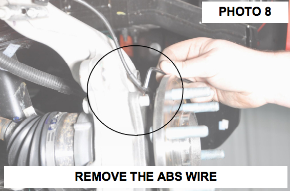
Step 11: Remove the ABS wire from the bearing assembly using a 5mm allen wrench.
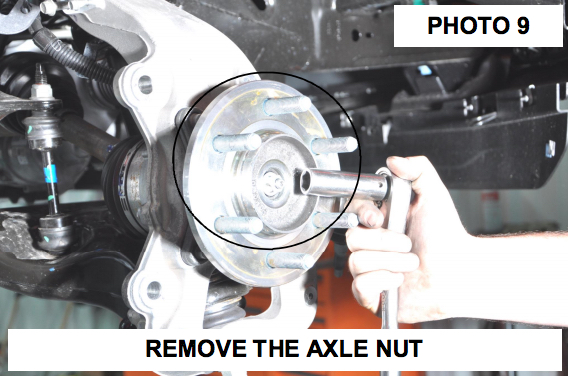
Step 12: Remove the axle nut using a 15mm socket. Retain hardware for reuse.
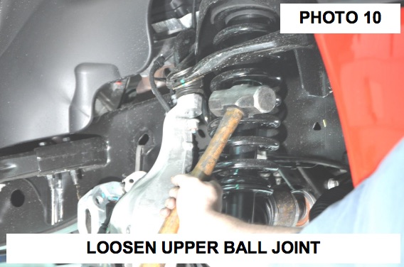
Step 13: Loosen the upper ball joint nut using a 21mm wrench. Use the appropriate tool to release ball joint from knuckle.
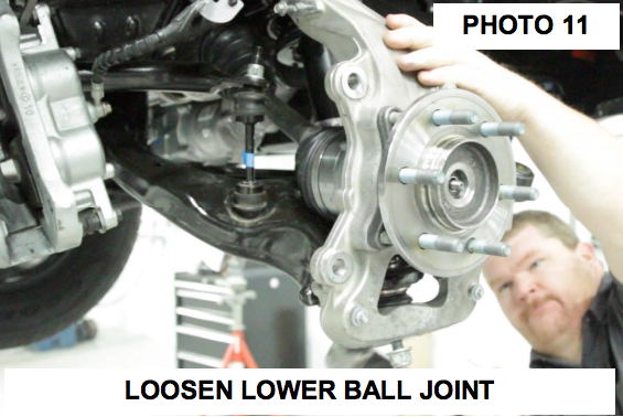
Step 14: Loosen the lower ball joint using a 24mm wrench. Use the appropriate tool to release ball joint from knuckle.
Step 15: Remove the upper and lower ball joint nuts and remove the knuckle from the vehicle.
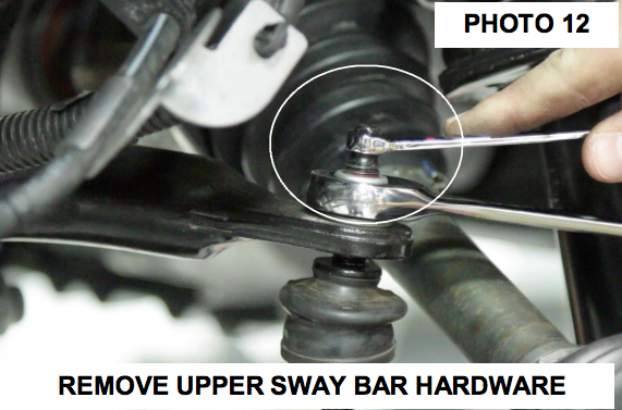
Step 16: Remove the sway bar links from the sway bar using a 8mm and 19mm wrench. Retain hardware for reuse.
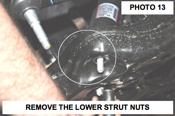
Step 17: Remove the lower strut nuts using a 18mm socket.
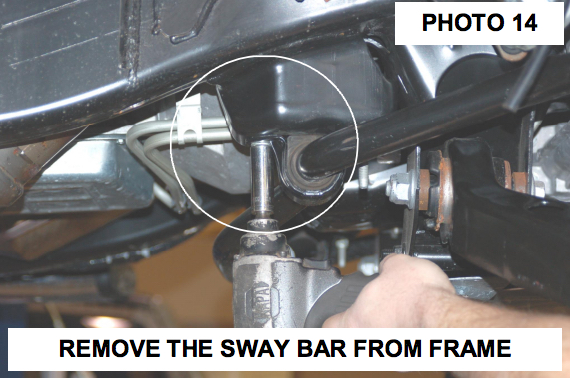
Step 18: Remove the sway bar from the frame mount using a 15mm socket. Please note the position that the sway bar is installed from the factory to make sure it is reinstalled correctly. Retain hardware for reuse.
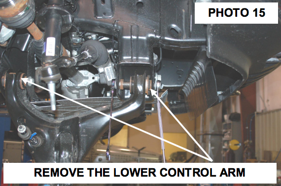
Step 19: Remove the lower control arm using a 21mm and 1-1/16” wrench. Retain hardware for reuse.
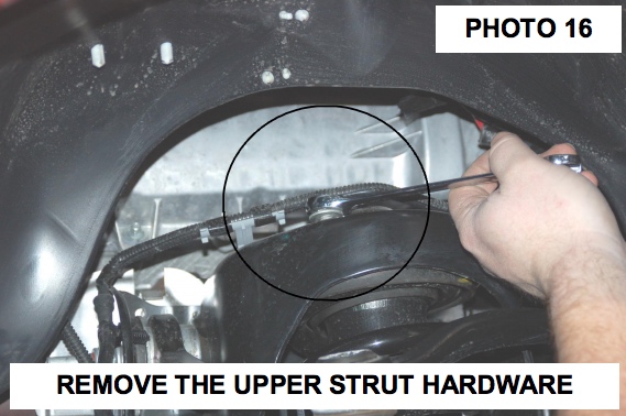
Step 20: Remove the strut from the upper mount using a 15mm socket / wrench. Retain hardware for reuse.
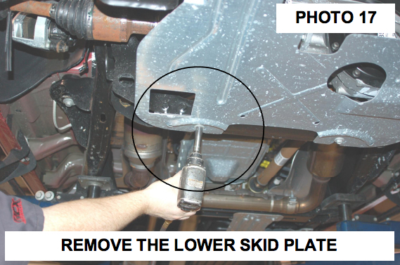
Step 21: Remove the lower skid plate if equipped by removing the 4 bolts using a 13mm socket.
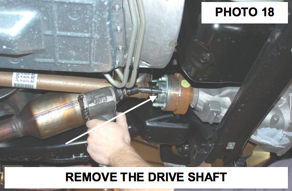
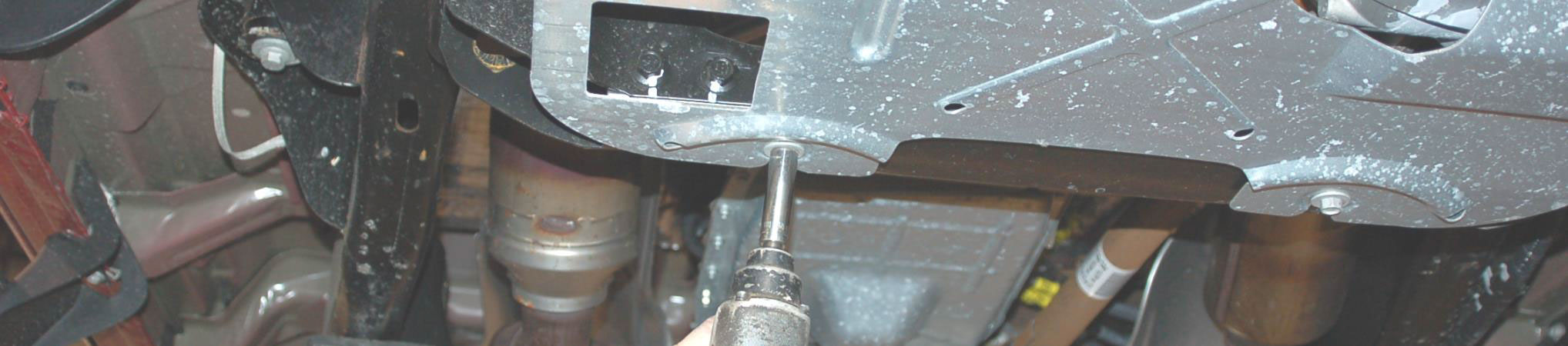
Step 22: Remove the driveshaft from the front differential using a 10mm socket. See Photo 18. Secure driveshaft out of the way.
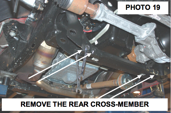
Step 23: Remove the stock rear cross-member using a 15mm & 18mm socket. Retain hardware for reuse.
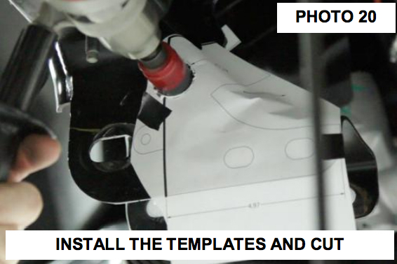
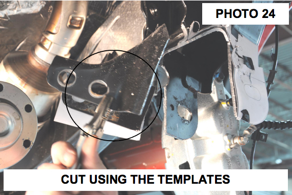
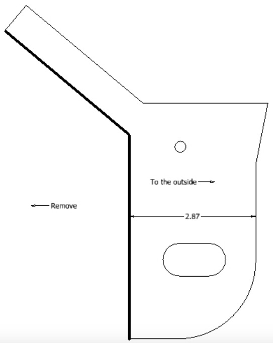
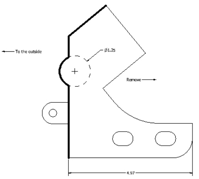
Step 24: Tape supplied cutting template on front and back side of the driver side lower cross-member mount. Using template as a guide, trim cross-member mount to allow the differential to be removed.
Step 25: Remove the differential vent tube from the differential.
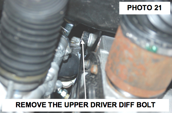
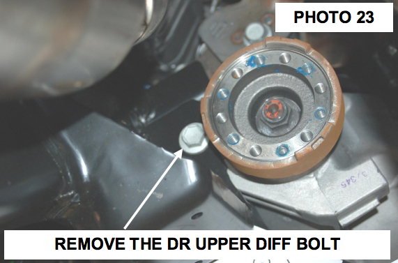
Step 26: Support the differential using a floor jack and remove the upper driver side differential bolt using a 18mm wrench. Retain hardware for reuse.
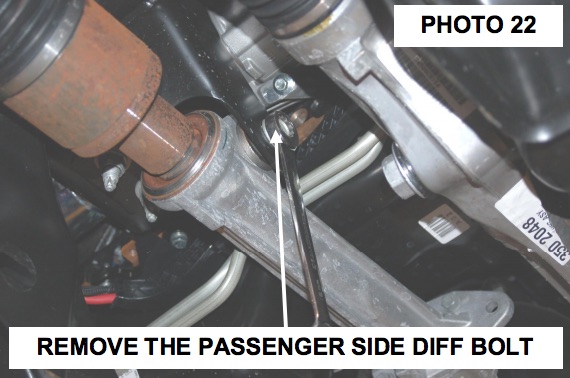
Step 27: Remove the passenger side differential bolt using a 18 & 21mm wrench. Retain hardware for reuse.
Step 28: Remove the lower rear driver side differential bolt using a 21mm socket / wrench. Lower and remove the differential from the vehicle.
Step 29: Complete the trimming of the frame on the driver side using the template and you can use a saw to cut the radius clearance or drill with a 1.25” hole saw before cutting the frame.
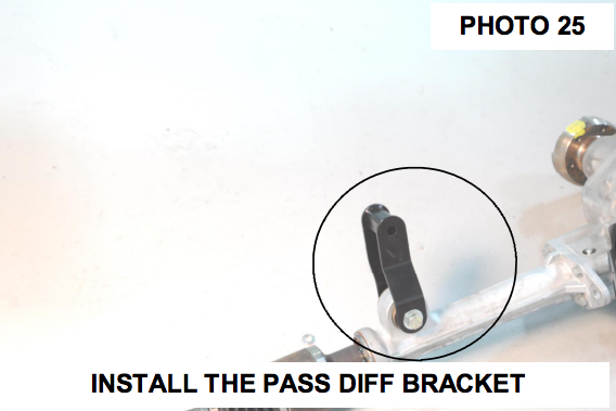
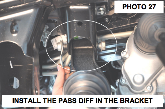
Step 30: Install the new bracket on the passenger side diff mount with the supplied hardware. Install the 9/16” x 4” bolt, washers & nut in the in the passenger side mount.
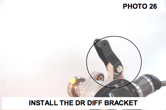
Step 31: Install the driver side diff mount with the supplied 9/16” x 4” bolt, washers and nut from the front to rear. NOTE: The differential mounts bolts will need to be inserted from the front of the differential in order to clear the rack and pinion.
Step 32: . Raise the differential into place and install the driver and passenger upper differential bolts using the stock hardware.
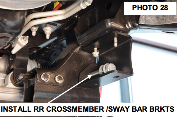
Step 33: . Install the rear cross-member with the supplied 18mm x 150mm bolt. The bolt will install through the sway bar bracket and rear cross-member, securing it to the stock location. Do not tighten at this time.
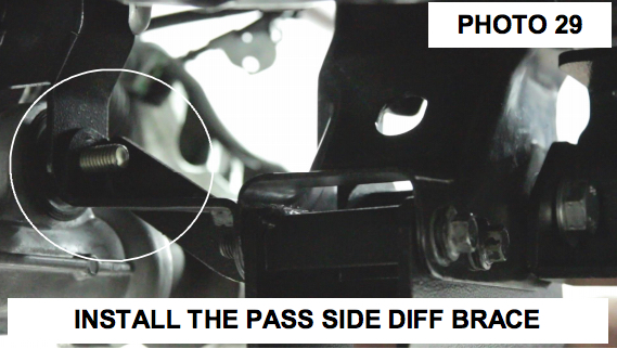
Step 34: Install the passenger side differential brace as shown in Photo 29 using the stock cross-member hardware. Do not tighten at this time.
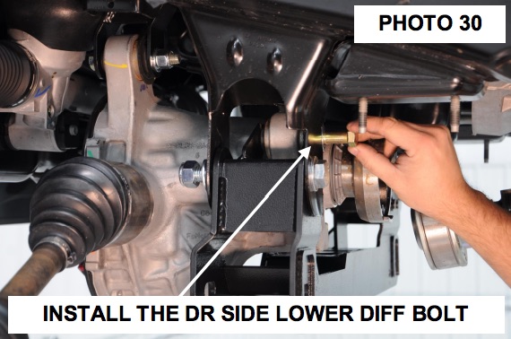
Step 35: Install the supplied 9/16” x 4” rear differential bolt through the sway bar mount and new differential mount.
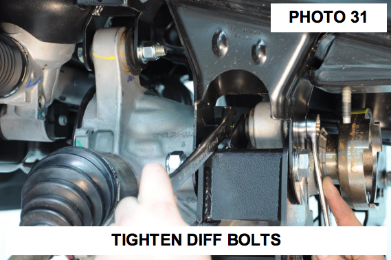
Step 36: Tighten the diff bolt with a 21mm and 22mm wrench.
Step 37: At this time tighten all diff bolts using 18mm socket / wrench for the upper diff bolts and a 21mm & 22mm socket / wrench for the new supplied lower diff bolts. Also tighten the passenger side diff brace hardware using a 15mm & 18mm socket /wrench.
Step 38: Reinstall the vent tube on the differential with the new supplied vent tube extension 1557Bag2.
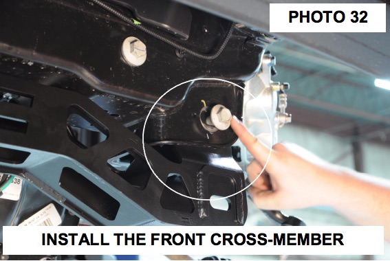
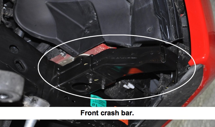
Step 39: Install the front cross-member using the factory hardware.
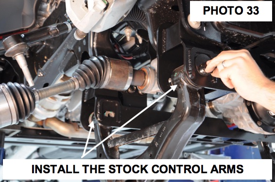
Step 40: Install the lower control arms using the supplied 18mm x 160mm cam bolts, cam washers and nuts.
Step 41: Install the new skid plate in the front and rear cross-members threaded holes using the supplied 3/8” x 1” bolts, washers. Tighten using a 9/16” socket
Step 42: Tighten all upper cross-member bolts using a 21mm, 1 1/16” socket and 1 1/16” wrench.
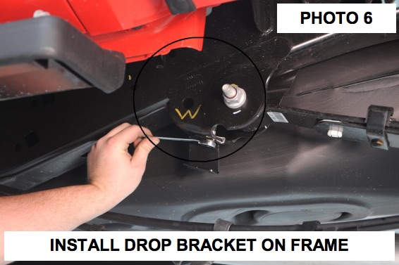
Step 43: Tighten the sway bar drop mounts to the frame using the factory hardware with a 15mm socket.
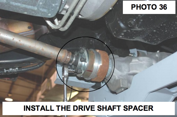
Step 44: Install the drive shaft spacer with supplied 10mm x 85mm hardware. Tighten using a 8mm allen wrench.
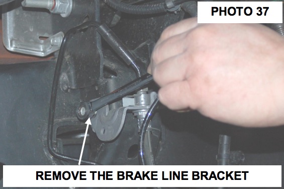
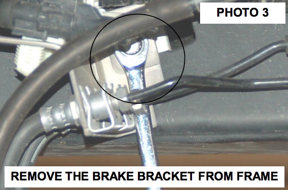
Step 45: Using a 10mm wrench remove the brake line bracket from the driver and pass side frame.
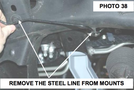
Step 46: On the passenger side remove the brake line from the two factory clips.
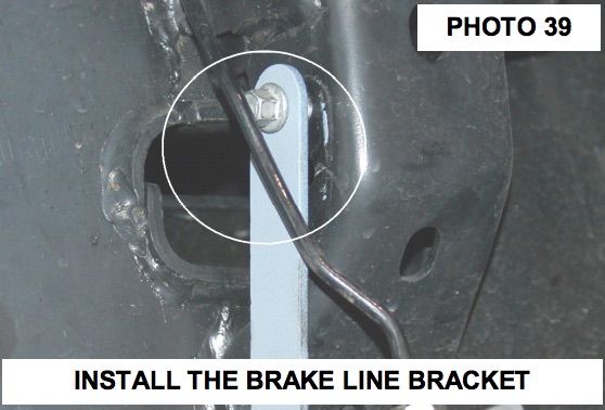
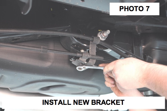
Step 47: Install the new brake line bracket on the driver and passenger side with the stock hardware.
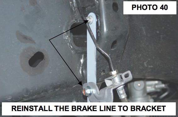
Step 48: Install the factory passenger side brake line in the new bracket using the supplied 5/16’ x 3/4” bolt, washer and nuts.
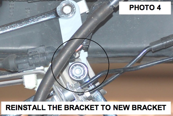
Step 49: On the driver side, pull slightly on the brake line to allow the line to be installed on the new bracket. Secure the brake line to the new bracket with the supplied 5/16” x 3/4” bolt, washers and nut.
Step 50: Using a 13mm socket / wrench, tighten the supplied brake line hardware and 10mm for the stock hardware.
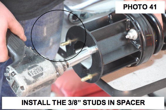
Step 51: Install the supplied 10mm studs in the strut spacers with a 17mm wrench.
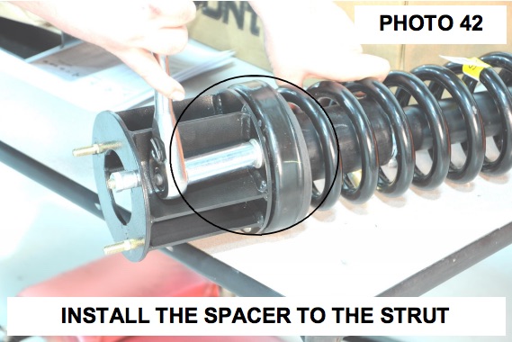
Step 52: Using the stock hardware, install the strut spacers on the struts. Tighten using a 15mm socket.
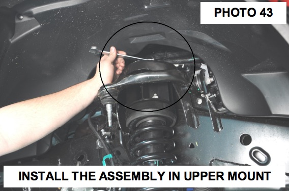
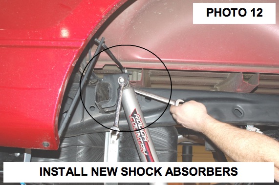
Step 53: . Install the strut with strut spacers installed in the stock upper mount. Secure with supplied 10mm nuts, washers and lock washers.
Step 54: Install the lower strut in the lower control arm using the factory hardware. Tighten using a 18mm socket.
Step 55: Tighten upper strut mount hardware using 17mm wrench.
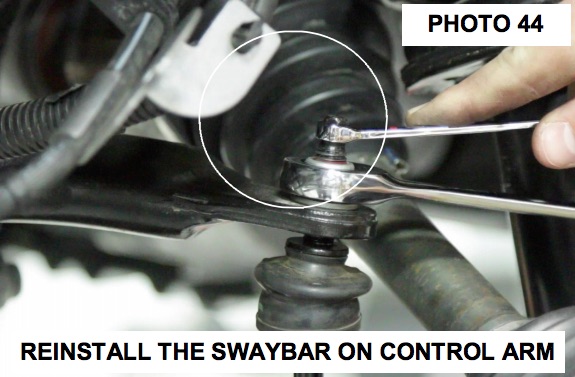
Step 56: Install the sway bar body on the sway bar links located on the lower control arms. Install nut to hold the sway bar in place but do not tighten at this time.
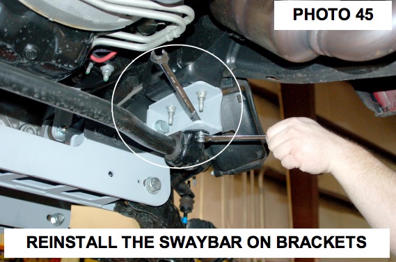
Step 57: Swing up the sway bar and install on the sway bar drop brackets using the supplied 7/16” x 1” bolts, washers and nuts. Tighten using a 18mm on the sway bar drop hardware and 18mm wrench on sway bar links on the lower control arms.
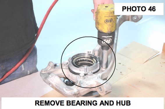
Step 58: Remove the stock bearing assembly from the stock knuckle using a 18mm for the bearing and a 8mm for the locking hub mechanism. Install the bearing assembly on the lifted knuckle using the stock hardware. Tighten using a 18mm wrench.
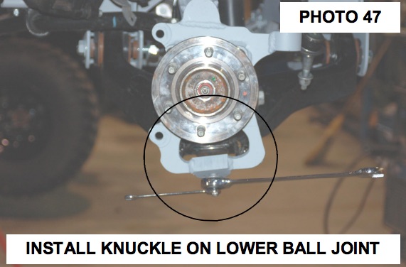
Step 59: Install the new knuckles using the stock hardware on the lower ball joints, tighten using 24mm and a 12mm wrench. Do not use air impact on the upper and lower ball joint, tighten with hand tools.
Step 60: Install IWE actuator on CV shaft
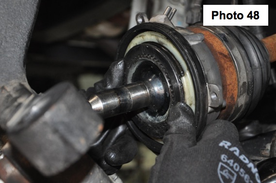
Step 61: Install CV shaft into the knuckle assembly.
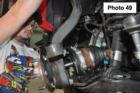
Step 62: Using a floor jack, raise the lower control arm and connect the upper ball joint on the upper control arm to the spindle. Using a 21mm wrench, torque to manufacturer specs. If ball joint turns while tightening, use a 3/8” wrench to hold the ball joint.
Step 63: Reinstall the steering linkage nut using a 21mm wrench.
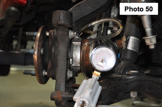
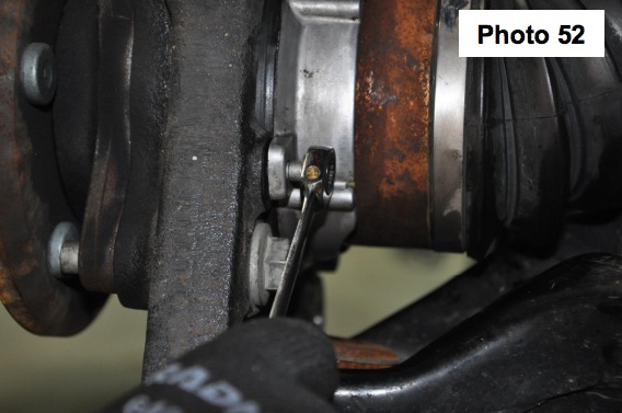
Step 64: Using a hand vacuum pump, apply and hold 24inHG of vacuum to the actuator through the large port.
Step 65: Install the (3) bolts securing the actuator to the knuckle and tighten using an 8mm wrench.
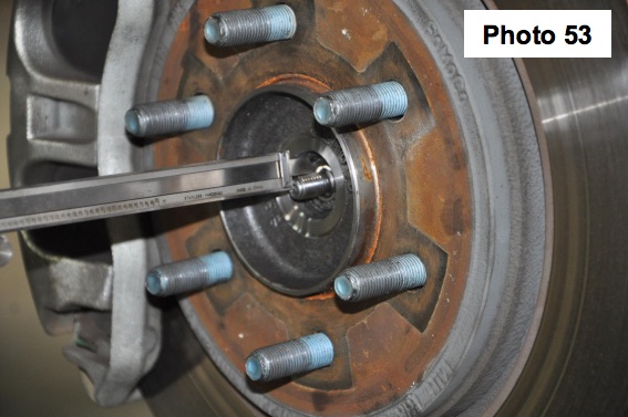
Step 66: With vacuum still applied to actuator. Measure the depth of the CV shaft treads protruding through the hub bearing. If minimum 15.5mm or .61” is not achieved, rotate the hub to eliminate binding of the splines.
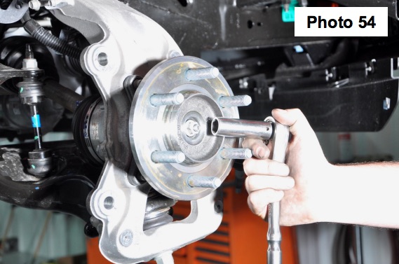
Step 67: Install axle nut and tighten to 30 lb.ft. Do Not Use and impact, caution must be taken or damage to shaft may occur.
Step 68: Verify free rotation of the hub with NO CV shaft rotation. No clicking or grinding noise should be present
Step 69: Release the vacuum from the actuator and rotate the hub to engage the actuator. You may hear/feel the actuator engage.
Step 70: Verify that the hub and CV rotate together. Reconnect the vacuum lines to the actuator.
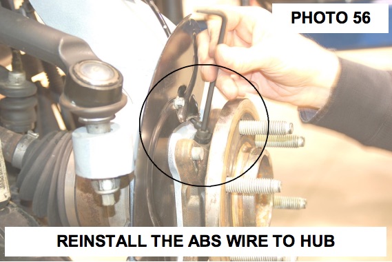
Step 71: Install the ABS wire on the bearing assembly using a 5mm allen wrench. NOTE: The factory dust shield will not be reused.
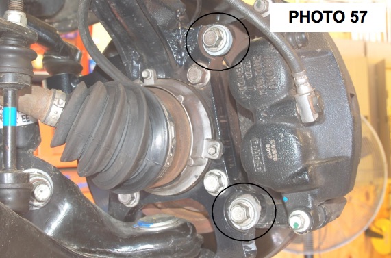
Step 72: Install the rotor and caliper on the knuckle with the stock hardware using a 19mm or 21mm wrench. Tighten hardware.
Step 73: Make sure the vacuum hose and ABS wire are out of harms way. Using the supplied zip tie, secure the vacuum hose and ABS wire to the knuckle neck.
Step 74: Install the tires and wheels using a 21mm socket. Remove the jack stands and lower the truck to the ground.
Step 75: Tighten the lower control arm bolts using a 1-1/16” wrench and socket. Torque to 200 ft/lbs.
