FREE 1 to 3-Day Delivery on Orders $119+ Details
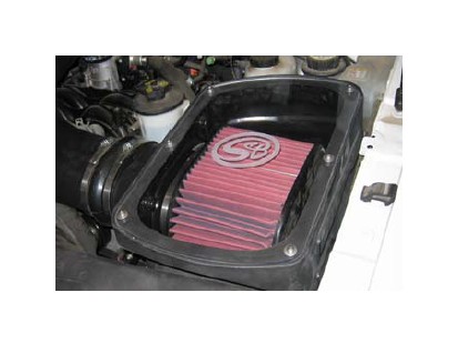
How to Install S & B Cold Air Intake w/ Oiled Cleanable Cotton Filter (04-08 4.6L) on your Ford F-150
Tools Required
- 1/2” Wrench & Socket
- Ratchet
- 5/16” Nut Driver or Flat Blade Screwdriver
- T-20 Torx wrench (supplied with kit)
- Phillips head screwdriver
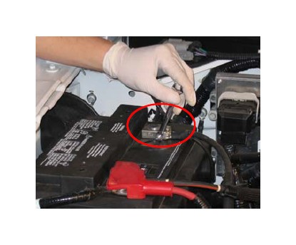
1. With the ignition switched off, disconnect the negative battery cable, use an 8mm wrench or socket.
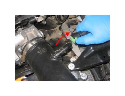
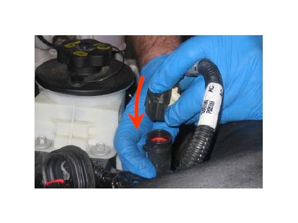
2. Disconnect the CCV line from the driver side valve cover to the OE intake tube and remove it from the vehicle.
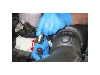
3. Disconnect the electrical connection for the MAF sensor at the pig tail coming from the OE intake tube.
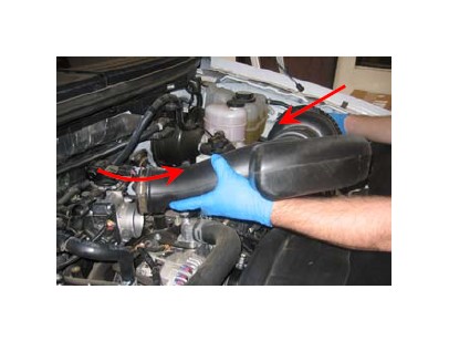
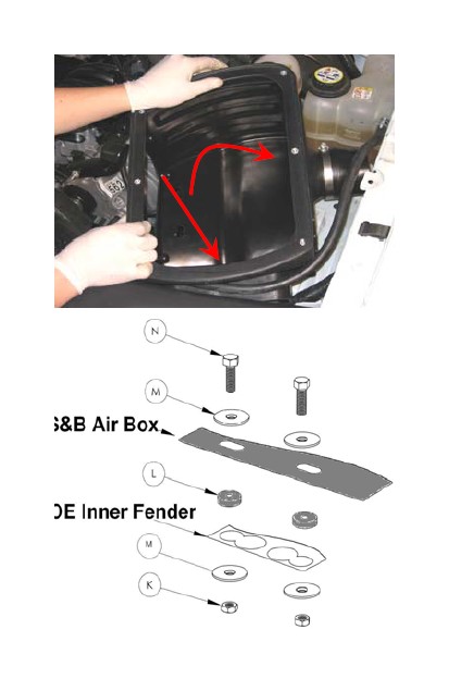
4. Loosen the hose clamp at the throttle body pull out and then towards the left, pulling the OE intake assembly out of the drivers side inner fender.
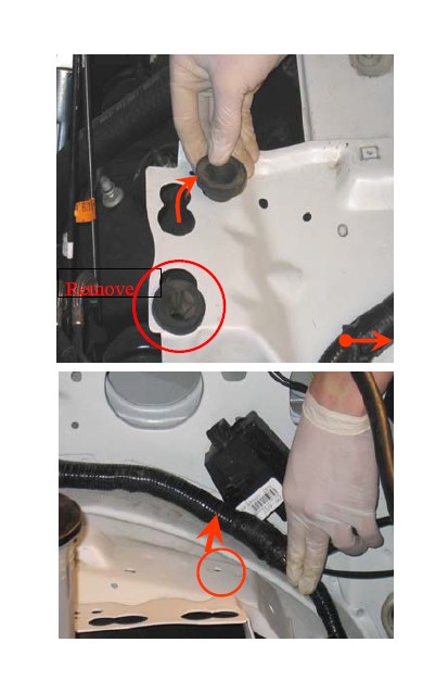
5. Remove the OE rubber grommets from the inner fender (drivers side) and relocate the wire loom closer to the fender.
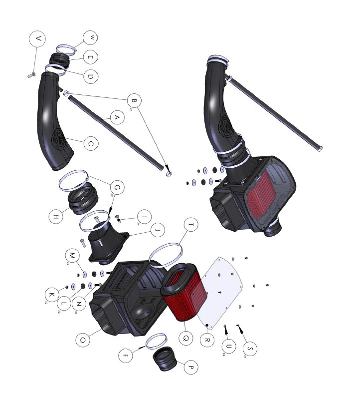
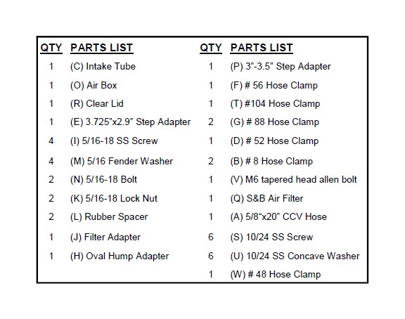
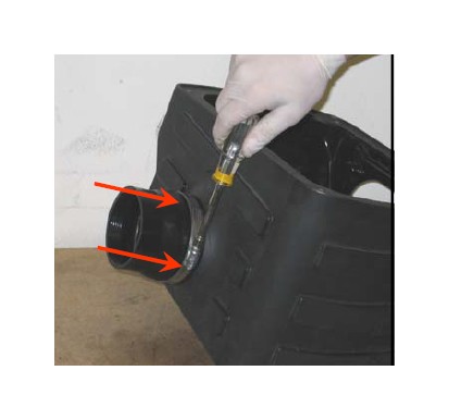
6. Install the 3” to 3.5” adapter (P) to the S&B air box fender snout (O), push on as far as it will go, secure with a #56 hose clamp (F).
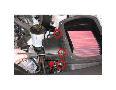
7. Install the S&B air box (O) and secure using the 5/16 bolts (N), fender washers (M), rubber spacers (L) and lock nuts (K) provided. See diagram below.
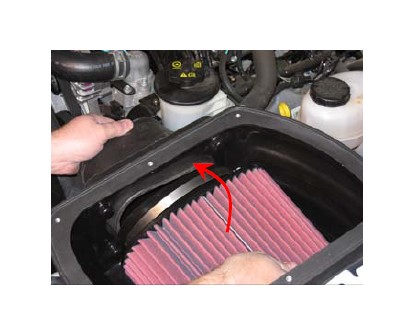
8. Place the S&B air filter (Q) inside the S&B air box (O). Offset flange is toward the front of the vehicle. Snap S&B filter adapter (J) into S&B air filter (Q) secure with #104 hose clamp (T). Use 5/16 nut driver or screwdriver.
9. Secure the S&B filter adapter (J) to S&B air box (O) with the 5/16 SS Phillips head screws (I) provided.
10. Place the Oval hump adapter (H) over filter adapter (J), do not tighten hose clamps at this step.
11. Install the step adapter (E) to S&B tube (C), secure with a #52 hose clamp (D).
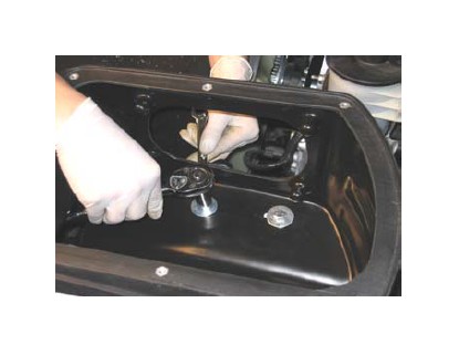
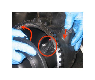
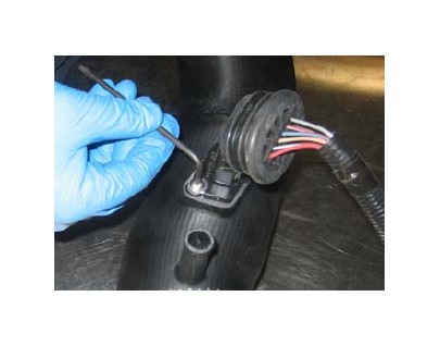
12. Remove the MAF sensor from OE air box; pull the rubber plug out then turn it sideways and push it through the hole, separate the housing and using the #T-20 Torx wrench supplied remove the MAF sensor.
Note: Direction of sensor related to air flow.
13. Install the MAF sensor into the S&B tube (C), secure with the OE screws, tighten evenly. Do not over tighten!
Note: Direction of sensor related to air flow.
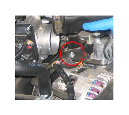
14. Remove the OE alternator bracket bolt just in front of the throttle body, and replace with the supplied M6 tapered allen bolt. This will allow clearance for the larger S&B tube.
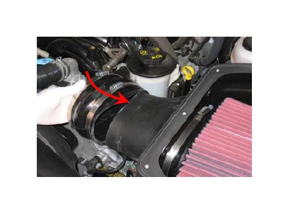
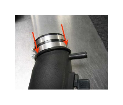
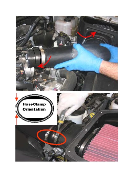
15. Install the S&B tube (C) into the Oval hump adapter (H) then onto the throttle body. Center the Oval hump adapter (H) over gap between tube ends and secure with #88 hose clamps (G) , then secure # 48 hose clamp (W) at throttle body.
Note: Position clamps as shown below.
16. Reconnect the MAF sensor electrical connection. Check that both connectors are fully engaged.
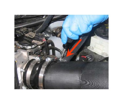
17. Install the S&B 5/8” CCV hose (A) from the valve cover to the S&B Intake tube (C), secure both ends with a #8 hose clamp (B).
18. Install the S&B clear lid (R), secure with 10/24 screws (S) and sealing washers (U). Do not over tighten.
19. Reconnect the battery. Inspect your installation, make sure kit is properly positioned and all fasteners are secure.
PERFORMANCE TESTING
∗ Engage parking brake and start your engine. Listen for abnormal noises. If an air leak is detected, re-inspect hoses and connections as they may need to be repositioned and tightened.
∗ S&B FILTERS RECOMMENDS THAT YOU KEEP YOUR OEM INTAKE SYSTEM IN THE EVENT IT IS REQURIED IN THE FUTURE.
∗ In order to maintain your warranty, all connections and components must be checked periodically for alignment and for proper tension on all connections. Failure to do so will void your warranty.
∗ Use only S&B Filter cleaning and oil products to service your filter. Using any other brand oil and or cleaners may void your warranty.