FREE 1 to 3-Day Delivery on Orders $119+ Details
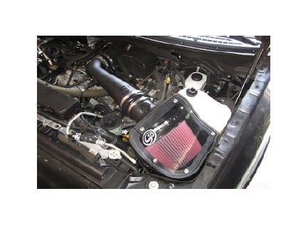
How to Install S & B Cold Air Intake w/ Oiled Cleanable Cotton Filter (09-10 5.4L, Excluding Raptor) on your Ford F-150
Tools Required
- 10mm, 13mm, 5/16” Wrench or Socket
- Phillips head Screwdriver
- 5/16” Nut Driver or Flat Blade Screwdriver
- Teflon tape
- Ford approved engine coolant (To top off new coolant reservoir if needed)
Shop Parts in this Guide
- S&B Cold Air Intake with Oiled Cleanable Cotton Filter (09-10 5.4L F-150, Excluding Raptor)
- S&B Cold Air Intake with Oiled Cleanable Cotton Filter (2010 5.4L F-150 Raptor)
- S&B Cold Air Intake with Dry Extendable Filter (09-10 5.4L F-150, Excluding Raptor)
- S&B Cold Air Intake with Dry Extendable Filter (2010 5.4L F-150 Raptor)
BEFORE YOU START
• Please read the entire product guide before proceeding.
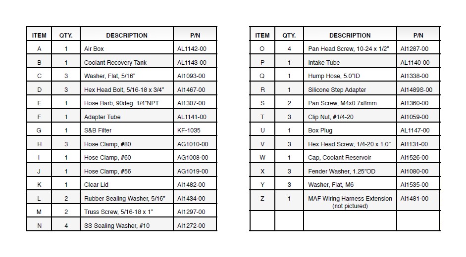
• Ensure all components listed on page 4 are present.
• If you are missing any of the components, call our customer support at (909) 947-0015.
• Do not work on your vehicle while engine is hot.
• Make sure the engine is turned off and the vehicle is in Park or the Parking Brake is set.
1. Be sure engine is cool before starting! With the ignition switched off and the parking brake set, disconnect the negative battery cable.

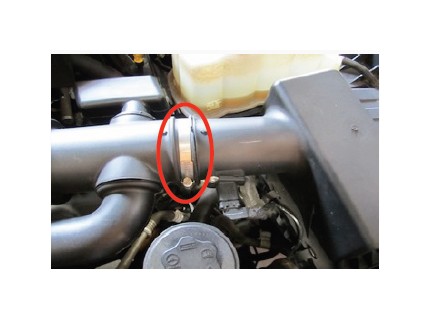
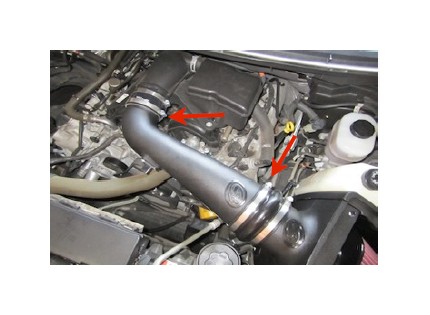
2. Loosen the hose clamp at the throttle body.
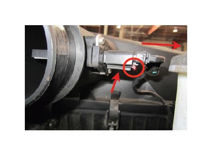
3. Disconnect the MAF sensor by sliding the red locking pin back, press in the bottom of the harness and pull out the male connection.
4. Loosen the hose clamp at the air box/ intake tube connection. Then remove the intake tube assembly from the truck.
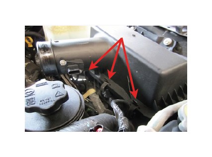
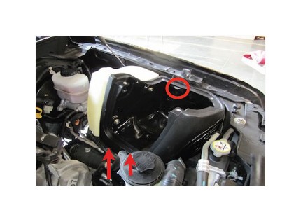
5. Undo the three clips holding the air box cover to the air box. Remove the air box lid and air filter from the truck.
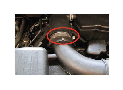
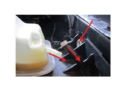
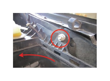
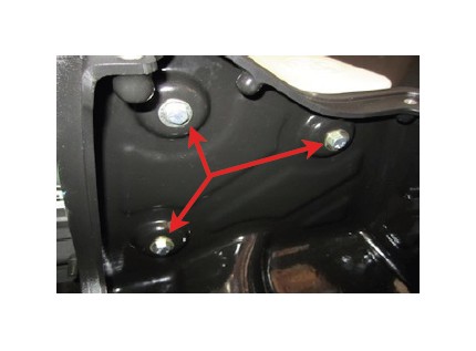
6. Using a 13mm socket, remove the rear air box mounting bolt. Then carefully remove the coolant overflow tube from the reservoir and use the mounting bolt as a temporary plug for the tube.
7. Remove the other air box mounting bolt using 13mm socket. Carefully tip the air box assembly away from the fender so that coolant isn’t spilt.
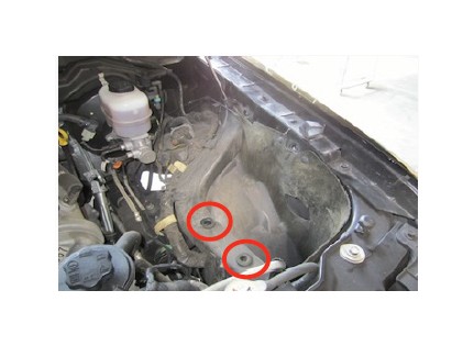
8. Pull the assembly out of the factory grommets and remove from truck. Note: You will have to remove the bolt from the rubber tube to fit through the air box assembly.
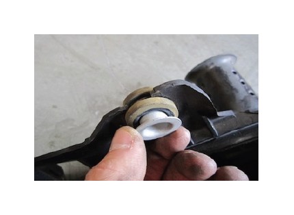
9. Remove the mounting insert and rubber grommet from the OE air box assembly.
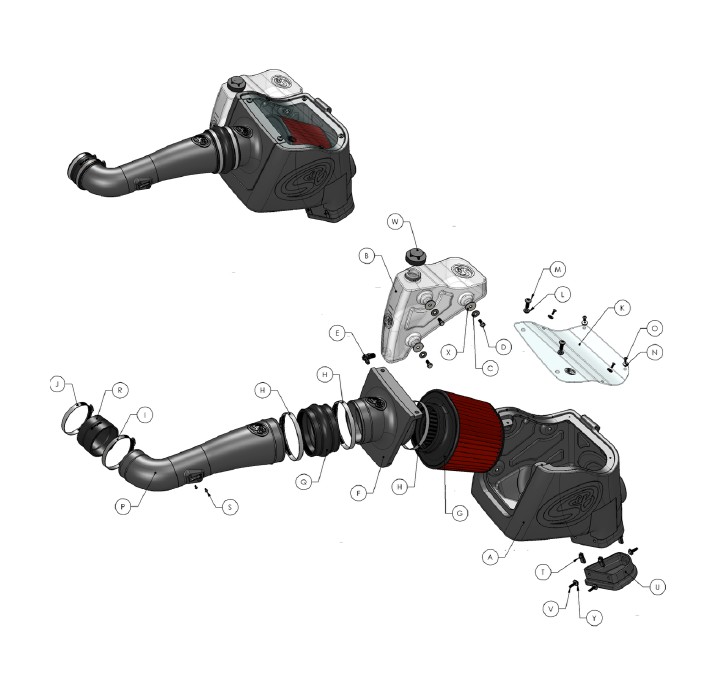
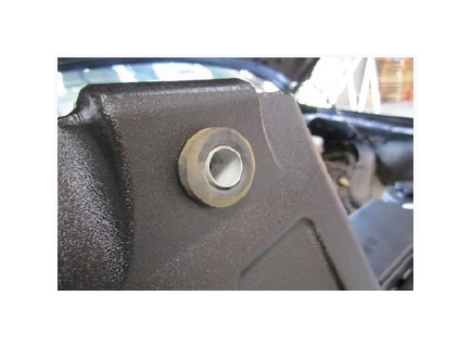
10. Insert the OE rubber grommet and insert to the Air Box (A) as shown.
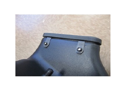
11. For those concerned about minimal engine heat; insert the three Clip Nuts (T) over the holes on the bottom opening of the Air Box (A), insert the Box Plug (U) into the end of the Air Box (A). Attach using the supplied 1/4-20 Hex Screws (V) and Flat Washers (Y) from the inside of the Air box using 5/16” socket or ratcheting wrench. For those seeking additional air flow, set the Air Box End Cap aside. (See page 4 for more info)
12. Apply Teflon tape to the threads of the 90deg. Hose Barb (E). Insert the Hose Barb into the Coolant Recovery Tank (B) as shown. Be sure the connection is tight.
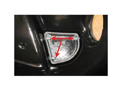
13. Place the three Large Fender Washers (X) into the indents on the side of the Air Box (A).
14. Place the Coolant Recovery Tank (B) on the side of the Air Box (A). Attach it using the supplied 5/16” Hex Bolts (D) and 5/16” Flat Washers (C).
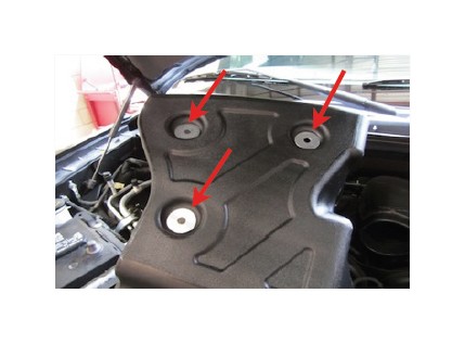
15. Install the Air Box/ Coolant Tank assembly into the truck. Push the prongs on the bottom of the air box into the OE grommets set in the frame. Secure the using the OE bolt removed in Step #7.
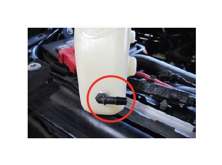
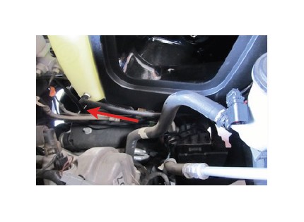
16. Remove the OE bolt that was inserted into the rubber coolant tube in Step #6 and push the tube end over the end of the 90deg. Hose Barb (E).
17. Remove the coolant from the OE reservoir and pour it into the Coolant Recovery Tank (B). Note: It may be necessary to add coolant to meet fill range of the new tank. Be sure to use Ford approved coolant. (See Page 4 for more info)
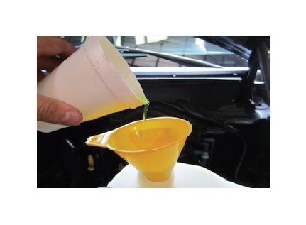
18. Attach the Reservoir Cap (W) to the Recovery Tank (B).
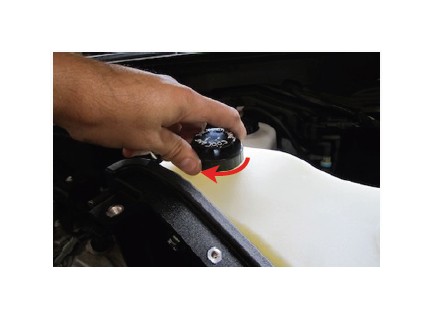
19. Insert the Adapter Tube (F) to the S&B Air Filter (G) as shown. Tighten the #80 Hose Clamp (H).
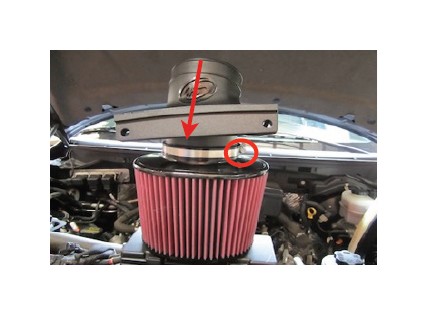
20. Slide the Filter assembly into the Air Box. Install two #80 Hose Clamps (H) over the Hump Adapter (Q). Push the Hump hose over the end of the Adapter Tube (F).
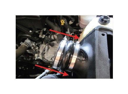
21. Install the small end of the Silicone Adapter (R) over the throttle body outlet. Secure using a #56 Hose Clamp (J). Loosely slide the #60 Hose Clamp (I) around the opposite end.
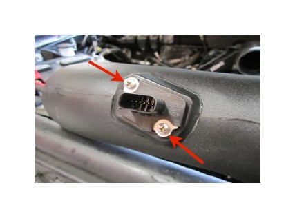
22. Remove the MAF sensor from the OE air box lid using the supplied Torx tool. With the small rubber OE ring gasket in place, install the MAF sensor into the Intake Tube (P) using the M4 Screws (S).
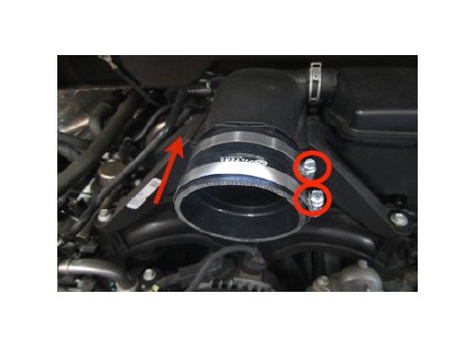
23. Install the Intake Tube (P) into the Silicone Adapter (R) and then slide the Hump Adapter (Q) over the opposite end. Secure all the hose clamps at this time.
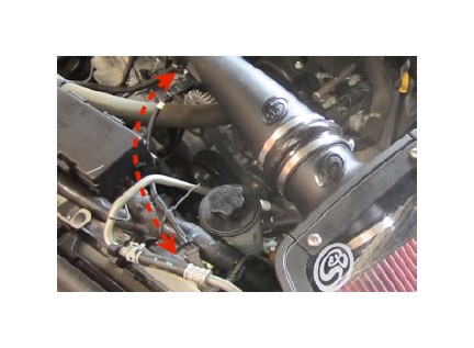
24. Install the supplied MAF sensor extension harness (Z) between the MAF sensor and the OE MAF connector. Use the supplied wire tie to position the harness away from any potential hazards.
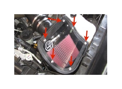
25. Remove the protective covering from the Clear Lid (K), then install the lid. Secure using the four 10/24” Screws (O), Sealing Washers (N), and two 5/16” Screws (M) and Rubber washers (L). Do not over tighten.
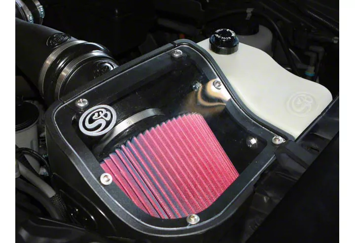
26. Reconnect the battery. Inspect your installation, make sure the kit is properly positioned and all fasteners are secure. The installation is now complete.
Air Box End Cap Testing
Stock air boxes are a significant contributor to poor air flow which is why S&B designs custom air boxes with secondary and/or enlarged openings. With that said, S&B recognizes the benefits of cooler air, so we have included a plug to seal off the opening if so desired. For optimal performance, we recommend that the intake be used without the end cap except in conditions of extreme heat.
PERFORMANCE TESTING
• Engage parking brake and start your engine. Listen for abnormal noises. If an air leak is detected, re-inspect hoses and connections as they may need to be repositioned and tightened.
• S&B FILTERS recommends that you keep your OE intake system in the event it is required in the future.
• In order to maintain your warranty, all connections and components must be checked periodically for alignment and for proper tension on all connections. Failure to do so may void your warranty.
• Use only S&B FILTERS cleaning and oil products to service your filter. Using any other brand oil and or cleaners on your S&B air filter may void your warranty.