FREE 1 to 3-Day Delivery on Orders $119+ Details
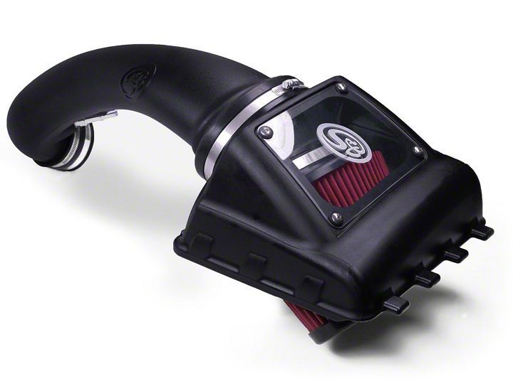
How to Install S & B Cold Air Intake w/ Oiled Cleanable Cotton Filter (11-14 5.0L) on your Ford F-150
Installation Time
30 minutes
Tools Required
- 8mm, 10mm, 13mm Wrench & Socket
- Pin Removal Tool or Flat Blade Screwdriver
- 7/16” Wrench and Socket
- 5/16” Nut Driver or Flat Blade Screwdriver
- Phillips Screwdriver
- 1 Set of Torx Wrenches & Allen Wrenches
- 1 Pair of Pliers or similar tool
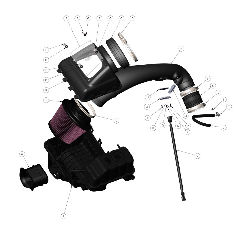
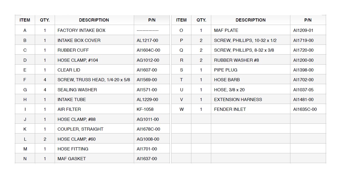
Shop Parts in this Guide
BEFORE YOU START
• Please read the entire product guide before proceeding.
• Ensure all components listed on page 4 are present.
• If you are missing any of the components, call our customer support at (909) 947-0015.
• Do not work on your vehicle while engine is hot.
• Make sure the engine is turned off and the vehicle is in Park or the Parking Brake is set.
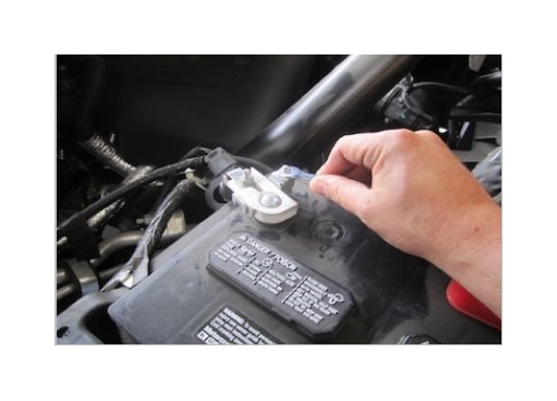
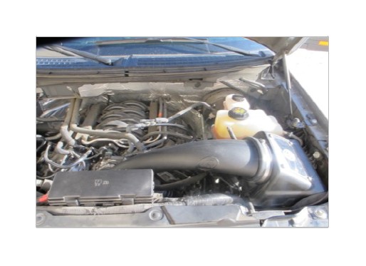
1. With the ignition switched off and the parking brake set, disconnect the negative battery cable on the passenger side. Note: Failure to disconnect the battery may cause the CEL to illuminate upon completion of the installation and subsequent operation. Do not skip this step!
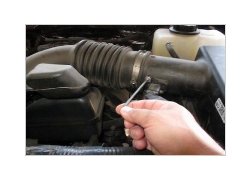
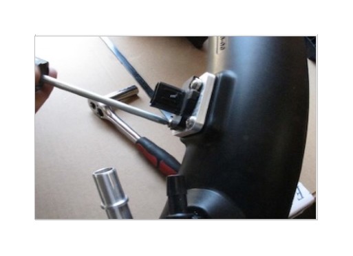
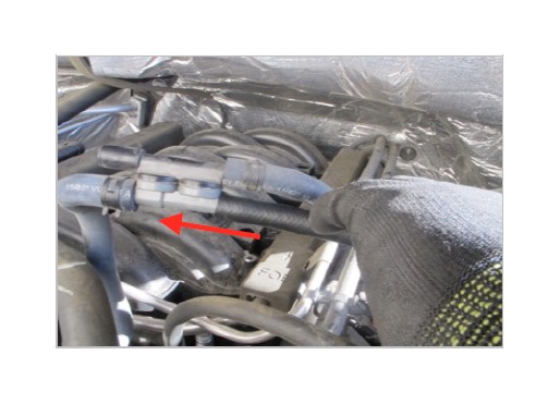
2. Use a Torx wrench to remove the sensor from the factory intake box cover.
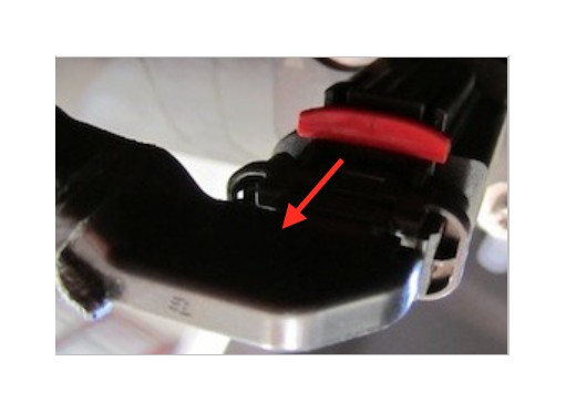
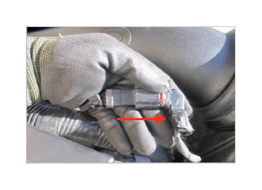
3. Disconnect the sensor from the harness by pulling the Red tab out and pressing down on the release button. Place the sensor in a safe location for later install.
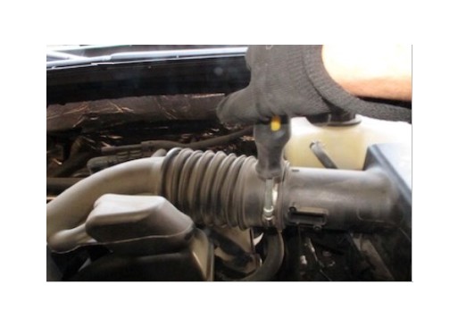
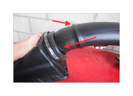
4. Use a 5/16” nut driver to loosen the hose clamp.
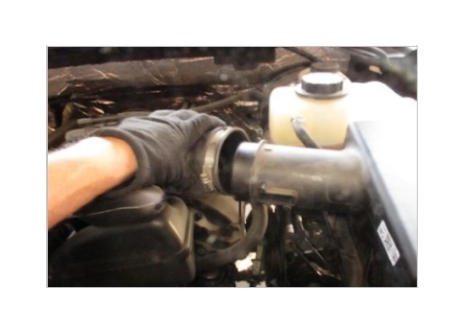
5. Once the hose clamp is loose, pull factory intake tube to the left to separate from factory intake box cover.
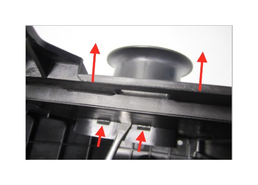
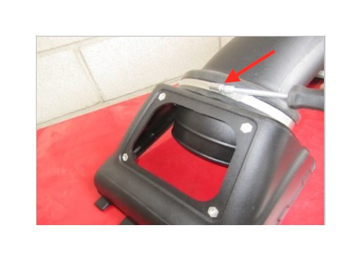
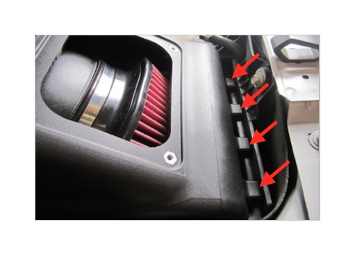
6. Remove the factory intake box cover by unsnapping the three metal latches that are on the side of the factory intake box.
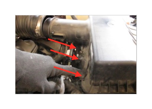
7. Lift to remove the factory intake box cover.
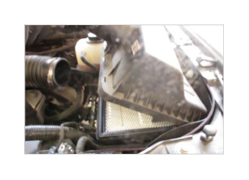
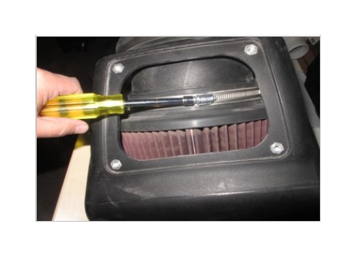
8. Remove the factory air filter.
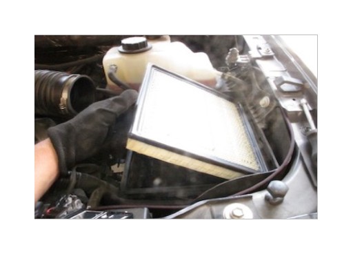
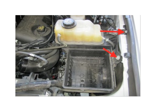
9. Remove the two mounting bolts securing the air intake intake box to get to the side air inlet. Remove the factory intake box from the vehicle.

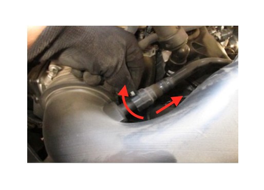
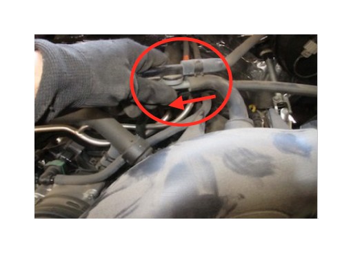
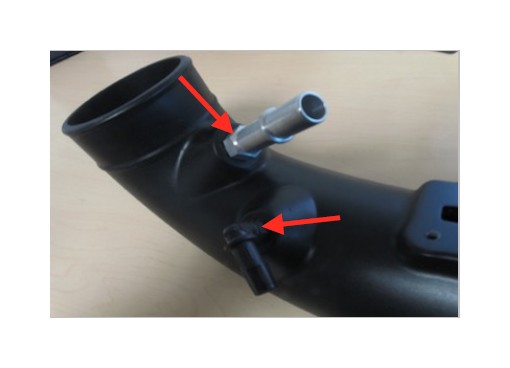
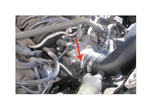
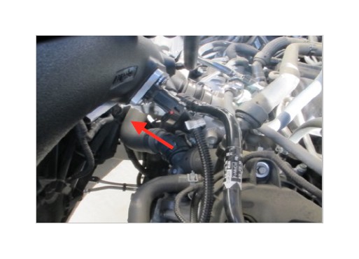
10. Near the throttle body, disconnect the hose by twisting to unlock the latch and pulling out.
11. Disconnect the other hose toward the middle of the factory intake tube by pulling the hose off the plastic barb.
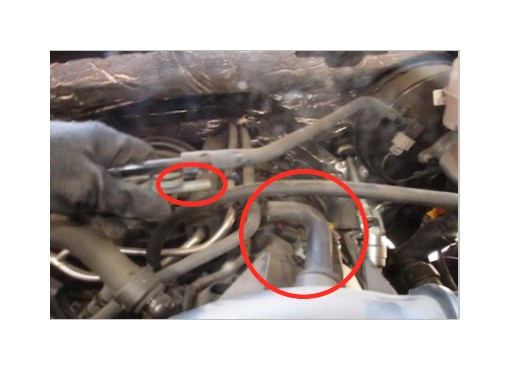
12. Loosen the hose clamp on the tube connected to the throttle body.
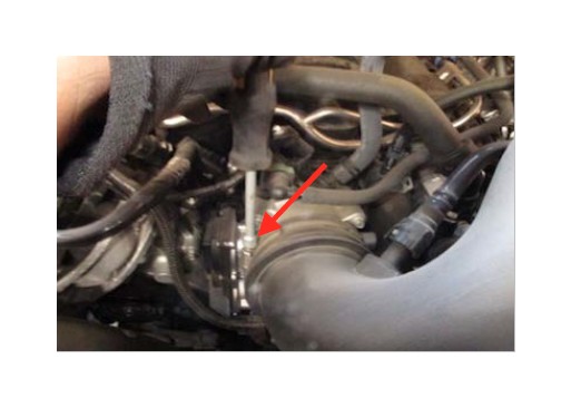
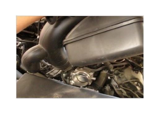
13. Remove the intake tube assembly from the vehicle.
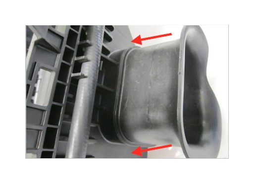
14. Remove the side inlet by pushing down on the tabs. A screw driver may be required to loosen the two tabs on top and one tab underneath.
15. Install the Fender Inlet (W) into the factory intake box by pushing in firmly until it snaps into place.
16. With the Fender Inlet (W) installed. Lower the factory intake box back down and reinstall the factory bolts. Make sure the fender inlet is pushed through the side skirt.
17. Install the Hose Fitting (M) and Hose Barb (T) into the Intake Tube (H). Install until snug and do not over tighten. Note: The orientation of the hose barb may need to be adjusted after the tube is installed.
18. Install the MAF Gasket (N) then the MAF Plate (O) and tighten down using the 10-32 Screws (P). Note: The arrows need to point towards each other.
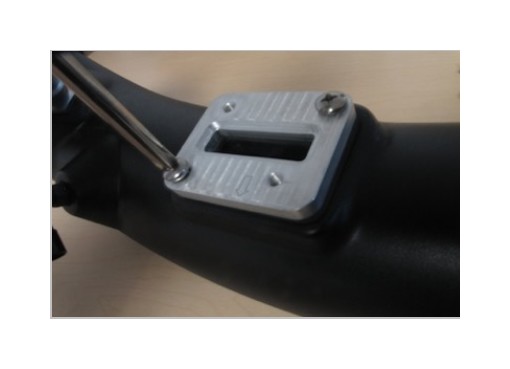
19. Install the MAF sensor using the 8-32 Screws (Q) and Rubber Washers (R) onto the MAF Plate (O).
20. Install the Coupler (K) and Hose Clamps #60 (L) onto the Intake Tube (H). Only tighten down the hose clamp on the tube side leaving the throttle body side loose for install.
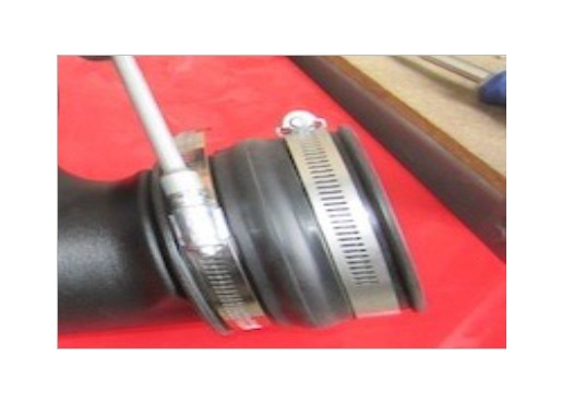
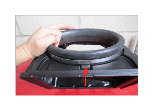
21. Install the Rubber Cuff (C) and Hose Clamp #104 (D) onto the Intake Box Cover (B) making sure that the tab on the cuff aligns with the notch.
22. Insert the Intake Tube (H) into the Intake Box Cover (B) through the Rubber Cuff (C). Please make sure that the tube is pushed all the way to the stop bead.
23. Tighten Hose Clamp #104 (D) on the Rubber Cuff (C). The rubber cuff will allow some movement of the tube to accommodate engine vibrations.
24. Install the Air Filter (I) onto the Intake Tube (H). Position the Hose Clamp #88 (J) so that it can be easily accessed through the lid opening. Tighten the hose clamp.
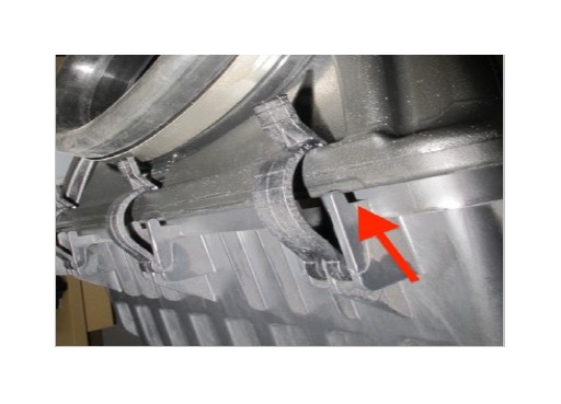
25. Install the whole intake assembly into the factory intake box. Make sure that the tabs on the Intake Box Cover (B) are lined up with the slots on the factory intake box. Once the tabs are in the slots lower the whole intake assembly. Proper installation into the slots will reduce movement.
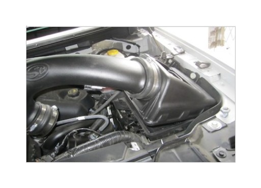
26. Fasten the three latches from the stock air box.
27. Slide the Intake Tube (H) onto the throttle body and tighten Hose Clamp #60 (L)
28. Connect the hardline from the engine to the Hose Fitting (M) and Hose (U) onto the Hose Barb (T).
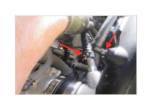
29. Connect the other end the Hose (U) onto the plastic barb.
30. Connect the Extension Harness (V) to the factory MAF harness.
31. Connect the Extension Harness (V) to the factory MAF sensor. Position the harness away from any moving or vibrating engine components.
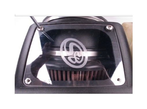
32. Remove the protective covering from the Clear Lid (E). Fasten the clear lid onto the Intake Box Cover (B) using 1/4-20 Screws (F) and Washers (G).
33. Reconnect the negative terminal on the battery. Inspect your installation, make sure the kit is properly positioned and all fasteners are secure. Affix the CARB and ID label near the intake kit. Keep all stock parts incase you would ever need to reinstall the stock intake. The installation is now complete.
34. Note: The optional Pipe Plug (S) is provided for custom application purposes.
PERFORMANCE TESTING
• Engage parking brake and start your engine. Listen for abnormal noises. If an air leak is detected, re-inspect hoses and connections as they may need to be repositioned and tightened.
• S&B FILTERS recommends that you keep your OE intake system in the event it is required in the future.
• In order to maintain your warranty, all connections and components must be checked periodically for alignment and for proper tension on all connections. Failure to do so may void your warranty.
• Use only S&B FILTERS cleaning and oil products to service your filter. Using any other brand oil and or cleaners on your S&B air filter may void your warranty.
WARNING!
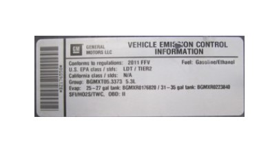
If your vehicle has a Vehicle Emission Control Information decal affixed to the factory airbox, a new replacement label must be obtained and installed in a readily visible position in the engine compartment in order to remain CARB compliant. Failure to do so will prevent the vehicle from passing a smog check. Replacement labels can be ordered from your local dealership. Regulations state that the VECI label shall not be affixed to any equipment which is easily detached from the vehicle. Label placement, under the hood on a painted surface is recommended.
EMISSIONS STANDARD
The California Air Resource Board (CARB) requires that an E.O. identification label be applied to the vehicle in order to pass a smog check inspection when a Performance Intake Kit has been installed. You must place the E.O. label provided on or near the intake kit after installation so that a smog check technician can easily verify the E.O. number. As of April 2009, S&B has never had a product where CARB denied an exemption request; however, the exemption process with CARB can take as long as 18 months. Check the status of the exemption process by looking up a specific part number at www.sbfilters.com. The CARB Exemption number and/or status is listed under the Product Details section for each part number. If the status shows as “Pending,” CARB has yet to issue an exemption. Products that have not been issued an EO number are street legal in most states, but may not be used on emission controlled vehicles in the state of California and are for off road use only. If you purchased your kit from S&B Filters directly, we will automatically mail you your Exemption Sticker when it is issued to us. If you purchased your kit from an authorized S&B Filters Dealer, log onto our web site and register to receive your Exemption Sticker.